Terminal connection diagram,
program 15
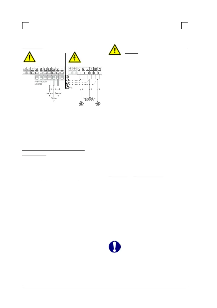
Fig. 3.2.16 “Universal 2x ∆T controller”
Caution
Relay R1: Only for speed con-
trol of standard pumps, mini-
mum load 20VA
Mains voltages 230VAC 50-60Hz
Connection in the right-hand terminal
compartment!
Terminal: Connection for:
L Mains phase conductor L
N Mains neutral conductor N
R1 Pump L (speed)
N Pump N
R2 e.g. pump L
N e.g. pump N
The PE protective conductor must
be connected to the PE metal terminal
block!
Sensor side
max. 12V
Danger
Caution
Mains side
230VAC
Brief description of switching function:
The ∆T function sensor 1 > sensor 2
switches the pump to relay R1.
The ∆T function 2 > sensor 3 switches
the pump to relay R2.
Installation
3 3
3.2 Electrical connection (continued)
Low voltage max. 12VAC/DC connec-
tion in the left-hand terminal compart-
ment!
Terminal: Connection for:
S1 Sensor 1 (control)
S2 Sensor 2 (ref.+control)
S3 Sensor 3 (thermostat)
S4 Sensor 4 ow heat meter
S5 VFS return heat meter
(yellow)
S6 VFS ow l/min
(white)
+ VFS +5V DC
(brown)
- jumper terminal block-
Connection of sensor earths (S1-S4)
and VFS (green) earth via terminal
block sensor-
The polarity of the sensors S1 to S4 is
freely selectable.
Caution
Vortex ow sensor installation
advice
To prevent damage to the Vortex ow
sensor it is strongly recommended to
install the sensor in the return! (see also
12.7 heat metering)
The VFS has to be installed in the cor-
rect ow direction!
For additional advice regarding the sen-
sors and the VFS see 3.3 „Installating
the temperature sensors“ on page 25.