3.3 Installing the temperature sensors
The Vortex Flow sensor is installed in the return ow. Special
attention to the ow direction and the maximum allowable
temperature (0°C to 100°C long-term and -25°C to 120°C short-
term) is required.
To prevent electrical interference and consequential damage/ in-
correct operation of the controller, the temperature sensor cables
should be separated from mains voltage cables
Caution
The controller operates with PT1000 temperature sensors which offer a
high degree of accuracy thus ensuring optimal control of system functions.
To further ensure the accuracy of heat metering, the PT1000 sensor should
be inserted in an immersion sleeve mounted in the uid. The temperature
sensor cables should be left inside the insulation for about 20 cm from the
measuring point to prevent cooling.
Caution
The PT1000 sensor cables can be extended to a maximum of 30m
using a cable with a cross-section of at least0.75mm². The cables
of the Vortex Flow sensors can be extended to 3 m.
Position the sensor precisely in the area to be measured!
Only use immersion, pipe-mounted or at-mounted sensors suitable
for the specic area of application with the appropriate temperature
range.
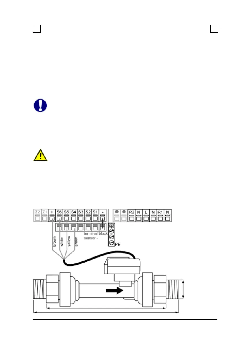
Electrical connection and dimensions of Vortex flow sensor VFS
a
b
c
VFS1-20 l/min
a:1/2 inch
b:155,50 mm
c:120,50 mm
Installation
3 3
3.2 Electrical connection (continued)
c
b
VFS2-40 l/min
a:3/4 inch
b:158,00 mm
c:123,00 mm