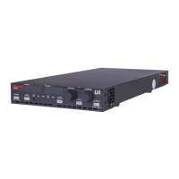
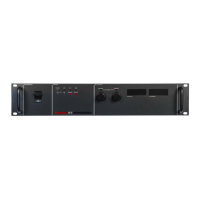
Do you have a question about the Sorensen DLM5-350E and is the answer not in the manual?
| Power Rating | 1750 W |
|---|---|
| Cooling | Forced Air |
| Humidity | 0-95% non-condensing |
| Protections | Overvoltage, Overcurrent, Overtemperature |
| Remote Sensing | Yes |
| Remote Programming | Yes |
| Frequency | 47 to 63 Hz |
| Dimensions | 19" W x 5.25" H x 20.5" D |
| Operating Temperature | 0°C to 50°C |
| Storage Temperature | -40°C to 70°C |
| Communication Interface | GPIB |
| Output Voltage | 0-350V |
| Output Current | 0-5A |
Outlines critical safety precautions for personal and equipment safety.
Warns about high energy and potentially lethal voltages during operation and servicing.
Emphasizes proper AC input grounding for shock hazard prevention.
Details precautions for operation, servicing, and preventing damage.
Guides on connecting the AC input power to the unit.
Outlines procedures for verifying unit operation after installation.
Covers Constant Voltage/Current modes and local programming.
Details how to set output voltage and current limit using front panel controls.
Provides a step-by-step procedure for setting voltage and current limits.
Details how to configure switches and connectors for advanced features.
Explains the front panel LOCAL/REMOTE switch and the J3 connector functions.
Explains how to remotely control output voltage and current limit.
Details how to use the front panel switch for remote programming.
Outlines methods for programming output voltage using 0-5V/0-10V sources.
Explains programming output voltage using a 0-5k ohm resistance.
Details methods for programming output current limit using 0-5V/0-10V sources.
Explains programming current limit using a 0-5k ohm resistance.
Describes how to remotely program only voltage or current limit.
Provides steps for remote voltage programming with local current/OVP control.
Provides steps for remote current limit programming with local voltage/OVP control.
Explains the OVP circuit for load protection and its configuration.
Details how to set and check the OVP trip level using front panel controls.
Explains how to program OVP using 0-5V or 0-10V external sources.
Describes the shutdown function for disabling/enabling output.
Provides guidance on troubleshooting common issues and contacting service.
Offers a diagnostic table for common symptoms and their solutions.


 Loading...