Do you have a question about the Sorensen DLM60-50E and is the answer not in the manual?
Details warranty terms, return procedures, and service policies.
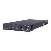
Overview of the DLM-E Series 3000 and 4000 watt power supplies.
Explains Constant Voltage and Constant Current modes with automatic crossover.
Lists key features such as voltage/current ranges and input options.
Electrical specifications for 3 kW DLM-E models.
Electrical specifications for 4 kW DLM-E models.
Further specifications including AC input, efficiency, and operating environment.
Physical dimensions, weight, output connector details, and input connector.
Recommendations and procedures for inspecting, testing, and installing the DLM-E Series power supply.
Crucial safety points for personal and equipment safety during installation.
Procedures for performing a physical check of the unit after unpacking.
Detailed description of front panel controls, connectors, and indicators.
Guidelines for proper placement, rack mounting, and ensuring adequate ventilation.
Instructions on determining AC input requirements and connecting the power cord.
Steps to perform initial tests for voltage and current mode operation.
Precautions and methods for connecting the load to the power supply.
Introduces local programming mode and covers Constant Voltage/Current operation.
Details Constant Voltage/Current modes and local programming procedures.
Explains how to use remote sensing for voltage regulation and compensation.
Outlines advanced features like remote programming, monitoring, and multiple supply configurations.
Details switch and connector functions for advanced setup and configuration.
How to program output voltage and current limit using external sources.
Explains OVP function and how to set/reset it via front panel or remotely.
Describes activating and programming the shutdown function via switch or DC/TTL signals.
Details readback signals and status indicators available for remote monitoring via J3 connector.
Covers configurations for series, parallel, and split supply operation.
How to disable front panel controls for exclusive remote operation.
Information on cleaning, calibration, and routine maintenance.
Guidance for diagnosing and resolving operational issues with the power supply.
Procedures for calibrating output voltage, current, and OVP using potentiometers.
Contact information and procedure for ordering replacement parts from Sorensen.
Lists the various fuse types, ratings, and sizes used in the DLM-E Series.
| Model | DLM60-50E |
|---|---|
| Type | Programmable DC Power Supply |
| Output Current | 0-50 A |
| Power Rating | 3000 W |
| Cooling | Forced Air |
| Protections | Over voltage, Over current, Over temperature |
| Remote Sensing | Yes |
| Remote Programming | Yes |
| Output Voltage | 0-60V |
| Frequency | 47-63Hz |
| Efficiency | 85% typical |
| Operating Temperature | 0 to 50°C |
| Storage Temperature | -40°C to 70°C |
| Humidity | 0 to 80% RH, non-condensing |
| Communication Interface | GPIB |