Do you have a question about the Sorensen DLM16-250E and is the answer not in the manual?
Outlines the requirements and procedures for claiming warranty service.
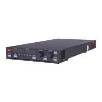
Provides a general overview of the DLM-E Series power supplies.
Explains the Constant Voltage and Constant Current operating modes.
Lists key features of the DLM-E Series power supplies.
Details the electrical and mechanical specifications of the power supplies.
Introduces the recommendations and procedures for installing the power supply.
Covers essential safety precautions for installation and operation.
Guides the user on performing a physical inspection after receiving the unit.
Describes the front panel and rear panel controls, connectors, and indicators.
Provides guidance on proper placement, mounting, and ventilation of the unit.
Details the requirements and procedures for connecting AC input power.
Outlines tests to verify proper operation after installation and before load connection.
Provides precautions and methods for connecting the load to the power supply.
Introduces basic operation concepts for the DLM-E Series power supply.
Explains standard operation in Constant Voltage and Constant Current modes.
Describes how to use remote sensing for voltage mode operation.
Introduces advanced features and procedures for DLM-E Series power supplies.
Guides on configuring remote functions using switches, connectors, and DIP settings.
Details how to remotely program output voltage and current limit.
Explains the Over Voltage Protection feature and its configuration.
Describes how to use the shutdown function via front panel or remote signals.
Covers remote monitoring of status indicators and readback signals.
Explains how to operate multiple DLM-E supplies in series, parallel, or split configurations.
Describes how to disable front panel controls for security or remote operation.
Provides guidance on periodic maintenance and cleaning procedures.
Offers methods for diagnosing and resolving operational issues.
Details the process and locations for calibrating output voltage, current, and OVP.
Provides information and contact details for ordering replacement parts.
Lists the specific fuse types, ratings, and sizes used in the unit.
| Output Current | 0 - 250 A |
|---|---|
| Power Rating | 4000 W |
| Cooling | Forced air |
| Protections | Overvoltage, Overcurrent, Overtemperature |
| Remote Sensing | Yes |
| Output Voltage | 0 to 16 V |
| Ripple and Noise | 5 mV |
| Efficiency | 85% typical |
| Operating Temperature | 0 to 40 °C |
| Storage Temperature | -40°C to +70°C |
| Communication Interface | RS-232 |
| Line Regulation | 0.01% + 2 mV |
| Dimensions | 19" x 5.25" x 17.75" (483 x 133 x 451 mm) |
| Input Voltage | 208 VAC ±10%, 3 Phase, 47-63 Hz |