Do you have a question about the Sorensen DLM40-75E and is the answer not in the manual?
Details hazardous voltages, caution for qualified personnel, and potential energy storage.
Outlines the terms and conditions for claiming warranty service for defective products.
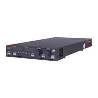
Overview of the DLM-E Series power supplies, highlighting technology and model naming.
Explains Constant Voltage and Constant Current modes and automatic crossover.
Lists key features including power ratings, input options, and AC power factor.
Details electrical parameters for 3kW and 4kW DLM-E models, including voltage, current, and noise.
Provides physical dimensions, connector types, and weight for DLM-E units.
Overview of recommendations and procedures for inspecting, testing, and installing the DLM-E Series power supply.
Important points for personal and equipment safety during installation and use.
Guide for physically checking the power supply and its components upon receiving it.
Detailed description and location of front and rear panel controls and indicators.
Procedure for connecting the DLM-E supply to the AC power source.
Steps to verify voltage and current mode operation and front panel controls before connecting load.
Precautions and considerations for connecting the load to the power supply.
Guidelines for selecting appropriate wire gauges based on current capacity.
Recommended load and sensing connections for a single load setup.
Methods for connecting multiple loads using radial or parallel distribution.
Details on Constant Voltage/Current modes and local programming control.
Procedure for connecting remote sense lines to compensate for load line voltage losses.
Details on front panel switch, J11 connector, and DIP switch functions for advanced control.
Methods for remotely setting output voltage and current limit using external sources.
Setting output voltage remotely using 0-5V, 0-10V sources or 0-5k ohm resistance.
Setting current limit remotely using 0-5V, 0-10V sources or 0-5k ohm resistance.
Details on setting and resetting the Over Voltage Protection circuit.
Enabling or disabling the supply's output using the STANDBY switch or remote signals.
Monitoring output voltage, current, and status indicators remotely.
Configurations for operating multiple DLM-E supplies in series, parallel, or split supply.
Disabling front panel controls for exclusive remote programming via J3.
Procedures for diagnosing and resolving issues with the DLM-E Series power supply.
Information on calibrating output voltage, current, and OVP using multiturn trimpots.
Table listing fuse types, ratings, sizes, and options for the DLM-E series.
| Brand | Sorensen |
|---|---|
| Model | DLM40-75E |
| Category | Power Supply |
| Language | English |