Do you have a question about the Sorensen DLM300-10E and is the answer not in the manual?
Overview of the DLM-E Series power supplies and their intended applications.
Explanation of the Constant Voltage and Constant Current operating modes.
Key features of the DLM-E Series power supplies, including power ratings and input options.
Detailed electrical and mechanical specifications for the DLM-E Series models.
Overview of recommendations and procedures for inspecting, testing, and installing the power supply.
Essential safety points for personal and equipment safety during installation and use.
Procedure for performing a physical check of the unit and its components after unpacking.
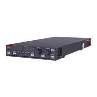
Identification and description of front panel controls, connectors, and indicators.
Guidelines for proper placement, mounting in racks, and ventilation requirements.
Instructions for connecting the power supply to the AC input power source.
Procedures for performing initial electrical and operational tests before connecting the load.
Precautions and methods for connecting the load to the power supply for reliable performance.
Introduction to basic operation including local programming and remote sensing.
Explanation of standard operation modes and front panel control procedures.
Procedure for connecting and utilizing remote sensing for voltage mode operation.
Overview of advanced features like remote programming, OVP, and multiple supply configurations.
Details on switches, connectors, and settings for remote operations.
Procedures for remotely setting output voltage and current limit using various methods.
Explanation of the OVP circuit and how to set and reset it.
How to use the shutdown function via front panel or remote inputs.
Information on remotely monitoring status indicators and readback signals.
Methods for configuring supplies in series, parallel, or split supply configurations.
Enabling front panel lockout to disable controls when using remote programming.
Guidelines for periodic maintenance, cleaning, and calibration of the power supply.
Procedures for diagnosing and resolving common operational issues with the power supply.
Information on calibrating output voltage, current, and OVP using internal potentiometers.
Information on how to order replacement parts from Sorensen's Service Department.
A listing of fuse types, ratings, and sizes used in the DLM-E Series power supplies.
| Brand | Sorensen |
|---|---|
| Model | DLM300-10E |
| Category | Power Supply |
| Language | English |