24 GB2 User Guide
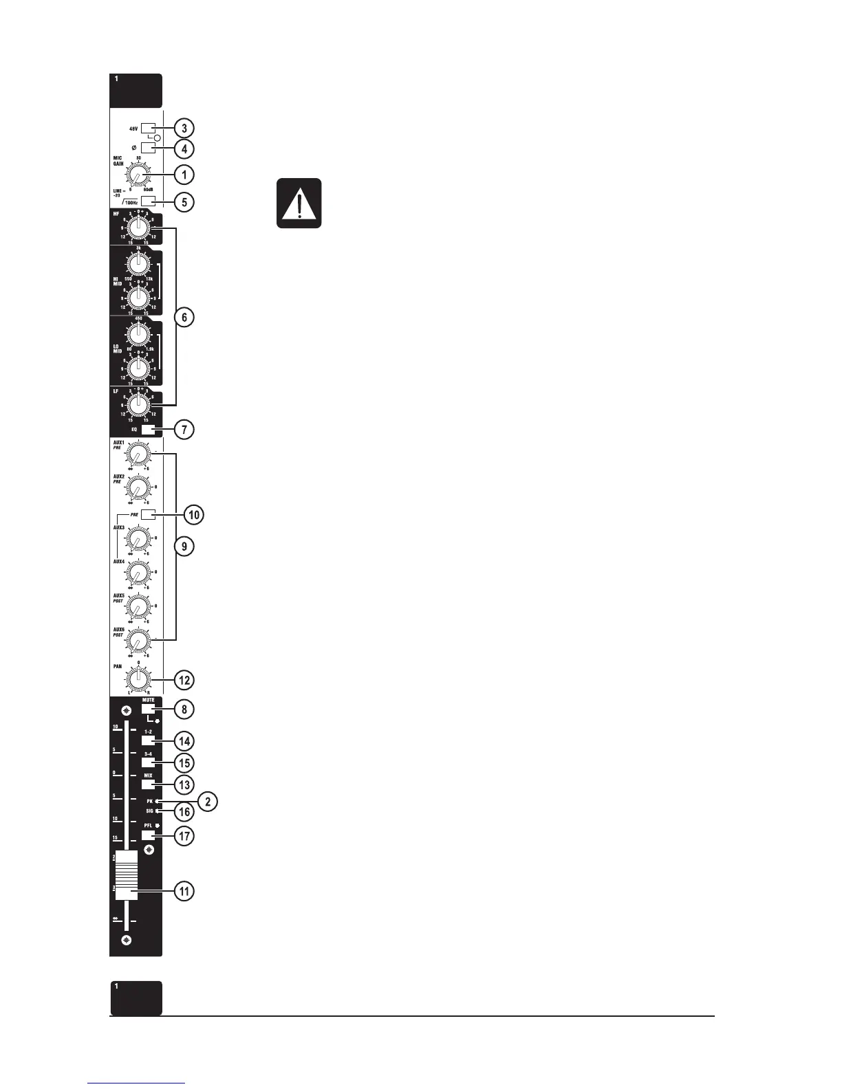
Mono Input
The MIC GAIN control (1) adjusts the sensitivity of both mic (XLR) and Line (1/4” jack) inputs.
Both inputs are electronically balanced, and are located on the rear connector panel.
The PEAK LED (2) monitors two points in the audio path: pre-insert point and post-EQ.
The 48V switch (3) applies 48V phantom power to the input XLR. An adjacent LED
indicates when the phantom power is on.
Don’t connect microphones with the phantom power switched on. Only switch the
phantom power on or off with the output fader down.
The PHASE switch (4) reverses the phase of the input.
The HI-PASS switch (5) enables the high-pass filter.
The module insert point is pre-EQ , pre-fader. It is located on the rear connector panel.
The EQ section (6) is four band, with shelving HF and LF, and swept peaking high and low mid
sections.
The HF and LF sections give +/-15dB cut/boost at 12kHz and 60Hz respectively. The Lo-mid
section gives +/-15dB cut/boost at 80Hz-1.9kHz. The Hi-mid section gives +/-15dB cut/boost at
550Hz-13kHz.
The section is switched in by the EQ switch (7).
The signal in the module is turned on and off by the MUTE switch (8). An adjacent LED illuminates
when the module is muted. All outputs from the module are muted, except for the Direct Output
if its Pre button is depressed. The PFL will still work whilst the module is muted.
Signal is sent to the AUX 1-6 busses via individual level pots (9). Aux 1 and 2 are both post-eq*
pre-fade feeds. Aux 3 and 4 are jointly selectable, via the PRE switch (10) to be pre-fade* or
post-fade feeds. Aux 5 and 6 are post-fade feeds*.
* Note: there is a dealer-implemented option to connect aux 1 and 2 feeds as pre-eq
pre fade. This would also affect aux 3 and 4 when they are selected as pre-fade.
Aux 5 and 6 may be connected to follow aux3/aux4 pre/post routing.
The warranty is voided if these options are implemented by anyone other than an
Authorised Soundcraft Dealer.
Post-fader signal level is controlled by a 100mm fader (11).
Signal for the mix and group busses are routed via the PAN pot (12). The pan pot positions the
signal within the stereo image.
The signal can be sent to the stereo mix busses (13), groups 1-2 (14) and groups 3-4 (15). Note
the use of groups 1 & 2, and groups 3 & 4 as 2 sets of stereo pairs.
A signal LED (16), next to the fader, meters the post-EQ, pre-mute signal.
The PFL switch (17) feeds the pre-mute signal to the monitor outputs and phones output. An
adjacent LED indicates when the PFL is on.
 Loading...