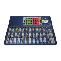
Do you have a question about the SoundCraft VI6 and is the answer not in the manual?
| Brand | SoundCraft |
|---|---|
| Model | VI6 |
| Category | Music Mixer |
| Language | English |
Guide to symbols used for safety warnings and important information.
Crucial safety instructions, including mains connection and earthing.
Detailed warnings regarding installation, operation, and maintenance.
Guidelines for safe audio monitoring to prevent hearing damage.
Information on product warranty, coverage, and limitations.
Details on mixing channels, insert points, direct outputs, and I/O options.
Information on connections, MIDI, and input/output processing capabilities.
Description of inputs, outputs, and miscellaneous controls on the surface.
Overview of the system's three main component parts: Stage Box, Local Rack, Console.
Details of the various connectors on the rear panel of the console.
Explanation of the Local Rack's role, how it works, and its front panel.
Description of the Stage Box, its cards, and connection to the Local Rack.
Diagram and explanation of system interconnections with Cat 5 breakout panel.
Diagram and explanation of system interconnections without Cat 5 breakout panel.
Rules for console operation and conventions used in the manual.
Explanation of screen areas, fields, and colour coding for functions.
Details on Vistonics knobs, function states, and control actions.
Operation of Solo/Sel keys and on-screen labelling methods.
Setting up bus types (Aux, Grp, Mtx) and formats (Mono/Stereo).
Using the Gang feature to link channels for simultaneous adjustments.
Overview of the signal path through an input channel.
Explanation of touch fields for parameter adjustment.
Detailed description of Gain, Trim, Filters, Format, Patch, and Delay fields.
Methods for pairing input channels to create stereo signals.
Details on the 4-band parametric EQ and its controls.
Explanation of Gate, Compressor, Limiter, and De-Esser functions.
Controls for Aux, Group, and Matrix busses, including levels and routing.
Controls for channel panning in LR and LCR modes.
Setting up and patching insert points for external processing.
Patching direct outputs to various output connectors.
Routing signals to gate key inputs and configuring matrix sources.
Configuring direct connections between input and output connectors.
Overview of output signal flow and general master section controls.
Details on processing for L, R, and C master busses.
Linking EQ and GEQ sections for easier adjustment of master busses.
Controlling output busses using master bay strips.
Controlling output busses via input bay strips in ALL BUSSES mode.
Controlling output busses using master bay Vistonics encoders.
Procedure for changing bus parameters via touch fields.
Detailed controls for the 4-band parametric EQ on output busses.
Dynamics processing (Compressor, Limiter) for output busses.
Pan settings and additional functions for output busses.
Overview of matrix signal flow and its configurable function.
Setting up matrix sources, points, and configuration.
Introduction to channel strip and master section encoders.
Selecting and using channel encoders for various functions.
Understanding VST encoder priority and changing their functions.
Controls for master bay encoders and layering of fader pages.
Using layers to access different views of the mixer's DSP structure.
Switching between input layers A and B for 64 input channels.
Accessing bus masters via master fader strips and ALL BUS layer.
Display modes for VCA and mute group assignments on strips.
How VCA groups affect member channels and their On/Off states.
Procedures for assigning channels to VCA and Mute Groups.
Diagram illustrating the signal flow within the patch system.
Table of patch locations and general rules for patch pages.
Connecting input connectors or MADI channels to input channels.
Connecting master or bus outputs to physical outputs or MADI channels.
Selecting and patching insert points, and setting up insert send/return signals.
Patching direct outputs to various output connectors.
Routing signals to the gate key input.
Connecting sources to create matrix outputs.
Configuring direct connections between input and output connectors.
Overview of monitoring outputs (Monitor A, B, Headphones) and parameters.
Controls for Solo Blend, Solo Trim, Phones Volume, and setup.
Configuring solo modes, sources, and miscellaneous settings.
Summary of Monitor A and B source options and functionality.
Explanation of AFL, PFL, SIP modes, and solo operation logic.
Managing solo priority and automatic cancellation of solos.
Using Follow Solo keys to adjust input channels contributing to outputs.
Controls for talkback and oscillator setup and routing.
Configuring oscillator parameters and patching outputs.
Routing talkback signals to outputs and monitor circuits.
Understanding input channel meters, gain reduction, and measuring points.
Details on bus master meters, output meters, and monitor meters.
Master section meter display, touch selection, and peak hold.
Accessing the main menu and its sub-pages like Main, Show, GPIO.
Console security lock and screen brightness adjustments.
Loading, saving, and managing shows and USB data.
Configuring General Purpose Input/Output channels.
Clock synchronization and tie line configuration.
Accessing FX, MIDI settings, and viewing the console log.
General console settings and system monitoring overview.
Controls for snapshot and cue management, including Store, Undo, Recall.
Setting up snapshots and cues, managing the snapshot pool.
Loading, copying, creating, and updating shows.
Explanation of what data is recorded in shows and snapshots.
Configuring GPIO channels for Local Rack and Stage Box.
Details on configuring GPI and GPO functions using VST keys.
Schematic diagram of the GPIO hardware.
Explanation of the FaderGlow feature and its colour coding.
Introduction to copying settings, pasting, and library management.
Principles of copying and pasting data selections and indicators.
Methods for copying channel or bus parameters.
Copying settings from Lexicon FX units.
Navigating and managing libraries, copying to and from libraries.
Specifications for audio channels, insert points, outputs, and I/O capability.
Specifications for connections, MIDI, and channel processing.
Specifications for inputs, outputs, and miscellaneous controls.
Summary of technical specifications including frequency response and noise.
Overview of the Vi Processor Card with Lexicon Effects and BSS Graphic Equalisers.
Simultaneous adjustment of all eight FX processors.
Assigning console keys to control FX tap tempo function.
Methods for patching FX processors as inserts or returns.
Selecting FX types from categories like Reverb, Delay, and Misc.
Detailed descriptions of Hall, Plate, Chamber, and Room reverb types.
Explanation of Pre Delay, Mid RT, Size, Diffusion, and Shape controls.
Descriptions of Studio, 2-Tap, Modulated, Mono, Pong, Tape, and Reverse Delays.
Controls for Tempo, Delay Time, Feedback, and Ducker.
Descriptions of Chorus, Flanger, Phaser, Vibrato, Rotary, and Pitch Shift.
Controls for Speed, Depth, Voices, Regen, Diffusion, and Waveform.
Details on the 35 BSS 30-band Graphic Equalisers for busses and masters.
