EasyManua.ls Logo

SOUNDMASTER PL525 - Unit Controls and Setup; Locations of Controls Overview; Installation and Connection

SOUNDMASTER PL525
11 pages
Print Icon
To Next Page IconTo Next Page
To Previous Page IconTo Previous Page
Loading...
PL525 / English Instruction Manual
2
LOCATIONS OF CONTROLS
1. Dust cover
2. Stop button
3. EQ button
4. Function knob
5. Skip down button
6. Record button
7. LCD display
8. Remote sensor
9. Play/Pause /ST/MONO button
10. Skip up button
11. Folder PRE
12. On-Off / Volume knob
13. USB socket
14. 3.5 mm aux-in jack
15. 3.5 mm headphone jack
16. MEM/CLK-ADJ button
17. Spindle adaptor
18. Tone Arm Lifting Selector
19. Turntable speed selector
20. Auto stop switch
21. Pick-up holder
22. Tone Arm
23. Line out socket
24. AC line cord
Caution:
Usage of controls or adjustments or performance of procedures other than those specified
herein may result in hazardous radiation exposure.
This unit should not be adjusted or repaired by anyone except qualified service personnel.
Installation
Unpack all parts and remove protective material.
Do not connect the unit to the mains before checking the main voltage and before all other
connections have been made.
Do not cover any vents and make sure that there is a space of several centimeters around
the unit for ventilation.
Connection
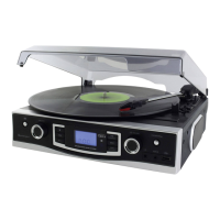
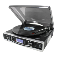
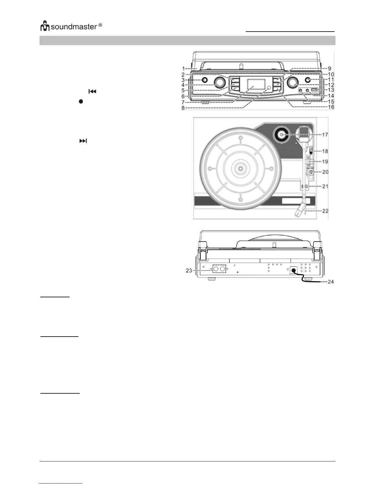
1. Connect the power cord (24) to AC outlet
2. When you first plug the unit into the mains, the LCD display (7) will show “ 0 : 00 ”.
3. Turn on the unit by ON/OFF/Volume knob (12), if the LCD display (7) is on with
backlighting, it means the power supply is normal. Now your system is ready to play the
music.

Other manuals for SOUNDMASTER PL525

Related product manuals