Page 10
For Technical Support - Please Call 1-800-338-7337
or visit www.soundoffsignal.com
500 Series Control System and Siren Amplifier
ENGSA5(xxxSx)Rev. D - 07/2021
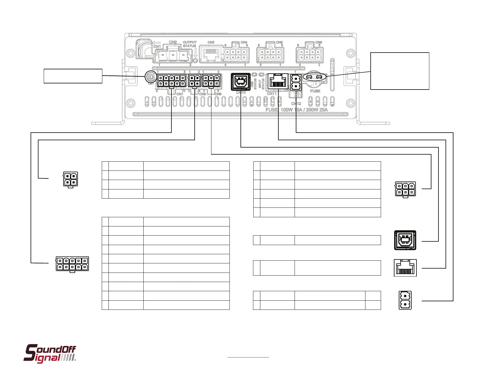
1 Orange/Black Igni�on Input - Fused at 3A
2 Blue Input 1 - Hi/Low
3 Lt. Blue Input 2 - Hi/Low/PWM*
4 Violet Input 3 - Hi/Low/PWM*
5 Brown Input 4 - Hi/Low/PWM*
6 Grey Input 5 - Hi/Low/PWM*
7 White Input 6 - Hi/Low
8 Green Input 7 - Hi/Low
9 Pink Input 8 - Hi/Low
10 Yellow bluePRINT Lin Bus - Remote Nodes, Input Node**
1 Orange Future Expansion
2 Light Blue / Red CAN A +
3 Blue Radio Rebroadcast / External PA Input 1
4 Light Blue / Black CAN Shield
5 Light Blue / White CAN A -
6 Blue Radio Rebroadcast / External PA Input 2
1 Orange Speaker A Out
2 Orange / Black Speaker A Out
3 Green Speaker B Out
4 Green / Black Speaker B Out
1 USB B Standard bluePRINT Programming Port
1 RJ-45 Port
bluePRINT Control Panel Bus - Remote Panel, bluePRINT
Link, bluePRINT Sync
1 Red Siren Amplier Power 15A/25A
2 Black System Ground
CN7 CN8
CN9 CN10 CN11 CN12
1
1
1
2
4
3
6
1
6
5
10
3
2
4
* See page 5 for more detail on PWM.
** When using a lightbar breakout box as an input node, it does not get connected to this
circuit.
Siren Amplifier Fuse
100w = 15A
200w = 25A
Future Expansion
 Loading...