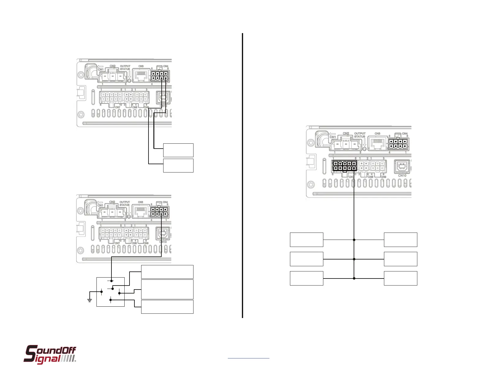
Remote Node
1
Remote Node
4
Remote Node
2
Remote Node
5
Remote Node
3
Input Node
Page 11
For Technical Support - Please Call 1-800-338-7337
or visit www.soundoffsignal.com
500 Series Control System and Siren Amplifier
ENGSA5(xxxSx)Rev. D - 07/2021
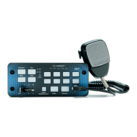
HORN RING EXAMPLES LIN BUS EXAMPLES
LIN Bus connections include Remote Nodes and Input Nodes. These can be
connected using the same wire, connected in parallel, or by using junction
points as shown below.
Input Nodes are only necessary when using additional discrete inputs beyond
the eight provided inputs from the 500 Series Control System.
A lightbar breakout box can be configured as an alternate input node. Lightbar
B.O.B.s cannot be connected here and must be connected as shown on page
12.
OEM Horn
Signal Wire
OEM Horn
Output Wire
85
30
87a
86
87
OEM Horn Signal Wire
Horn Ring Transfer
Output**
OEM Horn Output Wire
Low Current Horn Ring - 5A Max - Positive or Negative
High Current Horn Ring - Above 5A - Typically Positive
**Selected by programmer.
Bosch 332209150
Changeover Relay
(Or Equivalent - User Supplied)
 Loading...