Page 9
For Technical Support - Please Call 1-800-338-7337
or visit www.soundoffsignal.com
500 Series Control System and Siren Amplifier
ENGSA5(xxxSx)Rev. D - 07/2021
1
1 1
1
5 5
5
4 4
4
8 8
8
3
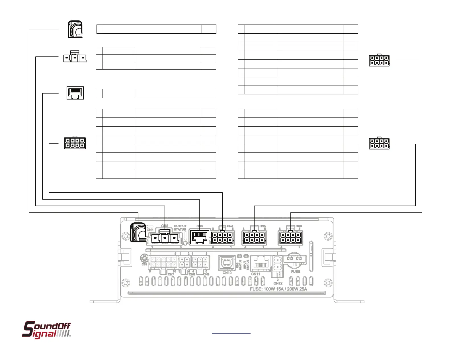
1 Main Power Input - Pass through to internal power lug* 75A Max
* Connec�on is on the inside of the amplier. See page 3 for more detail
*** Relay input is selectable between internal power and external source. See page 4
for more details.
** If running a posi�ve horn ring signal with more than 5A of draw, we recommend an
external horn ring transfer relay. See pages 4 and 11 for more informa�on.
† Connector terminals were changed from �n to gold at Jxxxxx. Do not mix alloy types.
**** Relay input is selectable between internal power and external source. See page 4
for more details.
1 Blue Relay Slide 1 20A
2 Green Relay Slide 2 20A
3 Yellow Relay Slide 3 20A
1 Green / Black Relay 3 - Ext. - Horn Ring Output** 5A
2 Green / White Relay 3 - Ext. - Horn Ring Input** 5A
3 Green Lightbar Bus Channel 2 - Internal B.O.B. -
4 White Output 15 5A
5 Blue
Output 11 ▲
(Diode Isolated)
5A
6 Brown
Output 12 ♦
(Inrush)
10A
7 Yellow Output 13 5A
8 Orange Output 14 10A
1 Green / Black Relay 1 - Normally Open 10A
2 Green / White Relay 1 - Normally Closed 10A
3 Green Relay 1 - External Input*** 10A
4 White Output 5 5A
5 Blue
Output 1 ▲
(Diode Isolated)
5A
6 Brown
Output 2 ♦
(Inrush)
10A
7 Yellow Output 3 5A
8 Orange Output 4 10A
1 Green / Black Relay 2 - Normally Open 10A
2 Green / White Relay 2 - Normally Closed 10A
3 Green Relay 2 - External Input**** 10A
4 White Output 10 5A
5 Blue
Output 6 ▲
(Diode Isolated)
5A
6 Brown
Output 7 ♦
(Inrush)
10A
7 Yellow Output 8 5A
8 Orange Output 9 10A
1 RJ-45 Lightbar Bus Channel 1 - Internal or External B.O.B.
CN1CN2 †CN3CN4
CN6 CN5
SCHEMATICS
= Diode Isolated
= Inrush
▲
♦
 Loading...