Page 7
For Technical Support - Please Call 1-800-338-7337
or visit www.soundoffsignal.com
500 Series Control System and Siren Amplifier
ENGSA5(xxxSx)Rev. D - 07/2021
Diagnostic Status LED Lights (Rear of Amplifier)
There are two different LED lights on the rear of the amplifier. Each
LED light represents a different portion of the siren function.
The upper light is marked “OUTPUT STATUS.” The lower light is
marked “INPUT STATUS.” Please see the below tables showing what
the codes mean.
The error code sequence start and finish is indicated by a long orange
pulse. In the case there is more than one code, a short orange pulse
is shown between codes.
Output Status Diagnostic Codes
Input Status Diagnostic Codes
Sequence OUTPUT STATUS Condition
Steady Green No Faults
Flashing Red Running in Boot loader Mode
1 Red, 1 Green Output Board Voltage Low
1 Red, 2 Greens Output Board Voltage High
2 Reds, 1 Green Comm Fault - Lightbar 1
2 Reds, 2 Greens Comm Fault - Lightbar 2
2 Reds, 3 Greens Comm Fault - Lightbar 3
2 Reds, 4 Greens Comm Fault - Controller Board
3 Reds, 1 Green Output Fault - Outputs 1-15
3 Reds, 2 Greens Output Fault - S1 - S3 Relays
3 Reds, 3 Greens Output Fault - R1 - R2 Relays
3 Reds, 4 Greens Output Fault - Horn Ring Relay
7 Reds, (x) Greens Special Code, Contact Tech Support
Sequence INPUT STATUS Condition
Steady Green No Faults
Flashing Red Running in Boot loader Mode
1 Red, 1 Green Output Board Voltage Low
1 Red, 2 Greens Output Board Voltage High
2 Reds, 1 Green Comm Fault - USB Port
2 Reds, 2 Greens Comm Fault - CAN Port
3 Reds, 2 Greens Comm Fault - Console Control Panel Port
2 Reds, 4 Greens Comm Fault - Output Board
2 Reds, 5 Greens Output Fault - Remote Control Panel Port
3 Reds, 1 Green Output Fault - LIN Data Bus (CN7.10)
4 Reds Configuration Fault
5 Reds, 1 Green Siren Speaker Fault - Siren A
5 Reds, 2 Greens Siren Speaker Fault - Siren B
6 Reds Output Fault
7 Reds, (x) Greens Internal Error Code
DIAGNOSTIC FUNCTIONS AND NOTIFICATIONS
Resetting Outputs
Should any of the solid state
outputs shut off due to a fault
condition, the output will need to
be reset. A diagnostic check should
be conducted prior to a reset.
Resetting can be done in three
different ways:
• Through the SoundOff Central
bluePRINT Software
• By pressing the reset button
shown at the top right of the
board
• By connecting the programmed
reset wire to ground typically
with a user supplied momentary switch. This function can be
programmed to any input, using SoundOff Central bluePRINT.
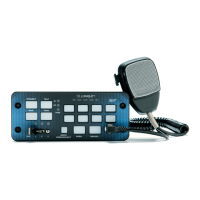
Diagnostic Status LED Lights (Control Panel)
The control panel can also indicate additional system faults, as
detailed in the below table.
S1 S2 Diag Condition
On On Flashing Over Temperature
Off On Flashing Under Voltage
On Off Flashing Over Voltage
Flashing Off Flashing Comm Fault - Relay
Off Flashing Flashing Comm Fault - Amp
Flashing Flashing Flashing Comm Fault - Relay & Amp
On Off Off* Speaker 1 Active
Off On Off* Speaker 2 Active
On On Off* Speaker 1 & 2 Active
Off Off Off*
Speaker 1, 2, or both is not
functioning.
*While the siren mode is active.
Reset Button
 Loading...