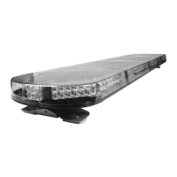
#EMG2000 MAGNUM™ DC LED Lightbar
EMG2000-DC 10.15
13
NORMAL OPERATION
Under normal operation with lightbar turned on the breakout box will have the Green and Red LED light on steady. When you change an input to the lightbar the Red
LED on the breakout box will flash then go back to steady.
When the lightbar is off (no input active) the Green LED on the breakout box will stay on for 15 seconds then go off putting the lightbar into sleep (standby) mode.
The Red LED will flash every 5 seconds to tell you there is power to the breakout box and it is waiting for an input to turn on the lightbar.
NO OPERATION
No LED on or flashing on Breakout box; Check input power and ground to lightbar, check data cable for damage and/or opens/shorts, check all 4
FH1-FH4 (10A) fuses on the electronic control board in lightbar. Check +Vdc is applied to a discrete input if
applicable.
Breakout box LED's operating correctly; Check all 4 FH1-FH4 (10A) fuses on the electronic control board in lightbar.
(see above)
NO OR INCORRECT INBOARDS OR CORNER LIGHTS (WARNING)
Breakout box LED's operating correctly; Check FH1-4 (10A) fuses on the electronic control board in lightbar.
No steady Red LED on breakout box; Check 24-pin connector at breakout box (insure it is snapped in correctly), check appropriate input to break
out box for output lights which should be on
No rear warning lights; Check that Arrow Warning Wire #9 front Breakout Box is being used if bar is set for arrow (after arrow dip
switch changes main power must be cycled). Check violet, red or tan lines from discrete harness are
connected to +Vdc if applicable.
Modules(s) stuck on or off; Check module is plugged in and grounded or module power shorted to ground or +Vdc.
NO TAKE DOWNS AUXILIARY OR ALLEY LIGHTS
Breakout box LED's operating correctly; Check FH1 and FH4 (10A) fuse on the electronic control board in lightbar.
No steady Red LED on breakout box; Check 24-pin connector at breakout box (insure it is snapped in correctly), check appropiate input to break
out box for output lights which should be on.
Module(s) stuck on or off; Check module is plugged in and grounded or module power shorted to ground or +Vdc.
With Discrete Wire Harness; Check Pink, Orange, and Brown wires are connected to +Vdc.
INCORRECT OR NO ARROW OPERATION
Breakout box LED's operating correctly; Check dip switches setting on the electronic control board in lightbar (after arrow dip switch changes main
power must be cycled).
No steady Red LED on breakout box; Check 24-pin connector at breakout box (insure it is snapped in correctly), check appropiate input to break
out box for output lights which should be on.
Arrow direction incorrect; Change passenger/driver side dip switch SW4 on the electronic control board in lightbar (after arrow dip
switch changes main power must be cycled).
8-wire control not operating; Check dip switch setting SW1-3 (should be off, off, off) on the electronic control board in lightbar (after arrow
dip switch changes main power must be cycled)
Rear Modules Incorrect or not operating; Check dip switch SW1-3 for proper arrow setting on the electronic control board in lightbar (after dip switch
changes main power must be cycled)
With Direct Connect Harness; Arrow is not available with Direct Connect Harness.
MAGNUM TROUBLESHOOTING
 Loading...