PIN#24 - Light Green/White
PIN#23 - Red Black
PIN#22 - Orange/White
PIN#21 - Yellow/White
PIN#20 - Brown
PIN#19 - Red/White
PIN#18 - Pink
PIN#17 - Red
PIN#16 - Orange
PIN#15 - Yellow
PIN#14 - Green
PIN#13 - Blue
Pink/White - PIN#12
Purple/White - PIN#11
Gray/White - PIN#10
Black/White - PIN#09
White - PIN#08
Purple - PIN#07
Brown/White - PIN#06
Light Green - PIN#05
Black - PIN#04
Gray - PIN#03
GreenWhite - PIN#02
Blue/White - PIN#01
Light Green/White 24 Left Turn Signal* Discrete Output #4*
Red/Black 23 Right Turn Signal* Discrete Output #3*
Orange/White 22 Rear Inboard 3 Discrete Output #2*
Yellow White 21 Rear Inboard 2 Discrete Output #1 (L)*
Brown 20 Front Takedown Front Takedown
Red/White 19 Alley Flash Alley Flash
Pink 18 Alley Driver Alley Driver
Red 17 Alley Passenger Alley Passenger
Orange 16 Front Inboard 3 Front Inboard 3
Yellow 15 Front Inboard 2 Front Inboard 2
Green 14 Front Inboard 1 Front Inboard 1
Blue 13 Front Corners Front Corners
Pink/White 12 Arrow, Left* Discrete Output #8 (R)*
Purple/White 11 Arrow, Center* Discrete Output #7*
Gray/White 10 Arrow, Right* Discrete Output #6*
Black/White 9 Arrow, Warning Discrete Output #5*
White 8 Pattern Select* Pattern Select*
Purple 7 Low Power Low Power
Brown/White 6 Front Takedown Flash Front Takedown Flash
Light Green 5 Auxiliary* Auxiliary*
Black 4 Cruise Lights* Cruise Lights*
Gray 3 Mode Select* Mode Select*
Green/White 2 Rear Inboard 1 Rear Inboard 1
Blue/White 1 Rear Corners Rear Corners
Wire Color
(Major Color/Stripe)
Pin#
Discrete Functions
(8 Wire Arrow Control)
Standard Functions
(4 Wire Arrow Control)
* - Reference page 11 for detailed explanation of functions
Note - Reference Switch table for explanation of what inputs are affected by
Active Low Switches
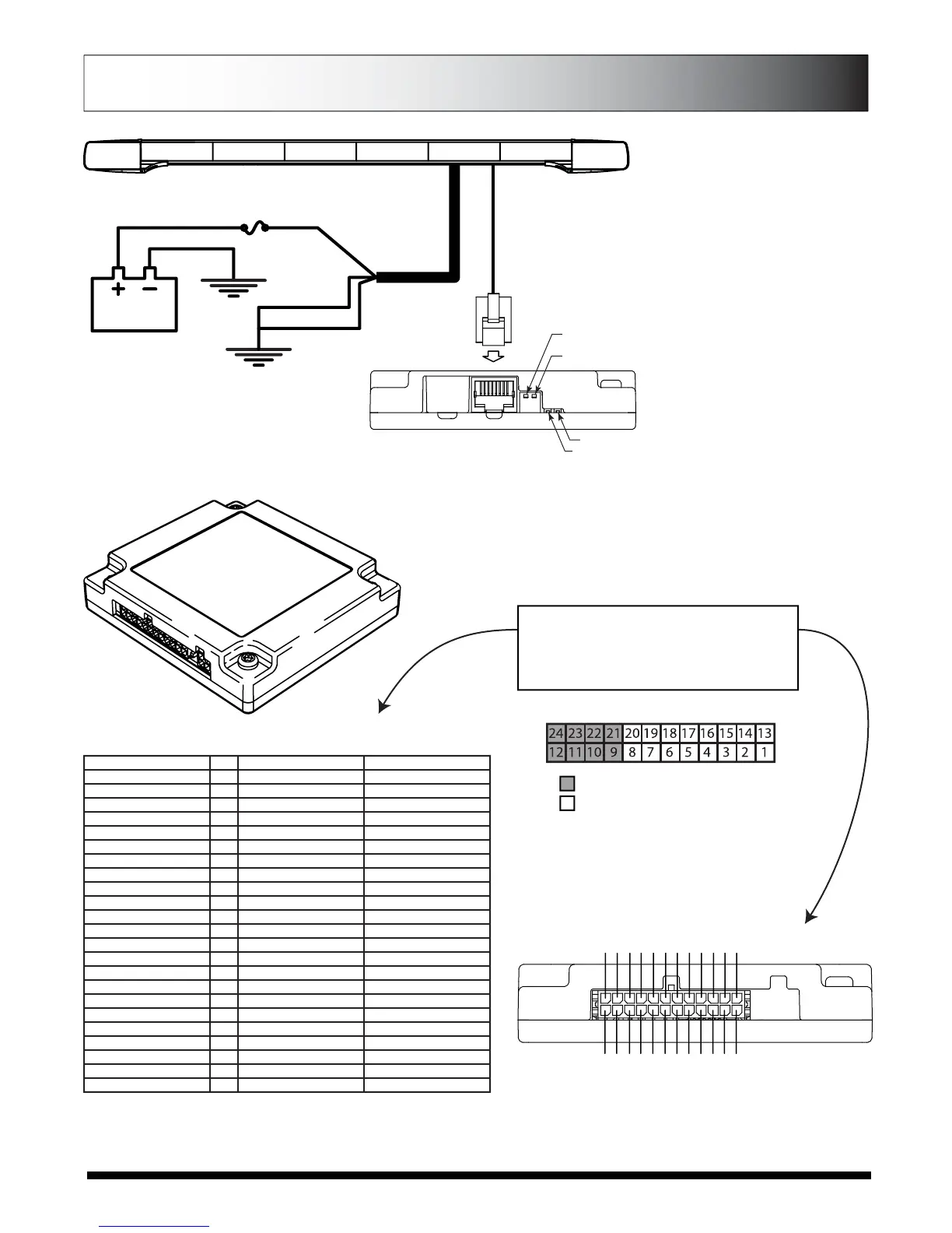
Functional Inputs
Fuctional inputs connect to your control head or
switching unit. Applying +12Vdc to any functional
input will activate it’s function (default-active high).
For more information, see switches explanantion on
second page.
Connector Pinning Chart
Controlled by Active Low Switch #2
Controlled by Active Low Switch #1
· When the switch is in the up position inputs connected to that switch are
active high. To activate an active high input, apply 12Vdc.
· When the switch is in the down position inputs connected to that switch
are active low. To activate the active low, apply ground (negative).
BREAKOUT BOX
DRAIN WIRE
BLACK 12 GA.
GROUND
40Amp FUSE
(Customer Supplied)
GROUND
POWER
CABLE
RED 12 GA.
RJ-45 CABLE
Active Low
Switch #1
Active Low
Switch #2
Red LED
Green LED
RED LIGHT
No Inputs Flashes Every 5 Secs.
Input Activated Steady On
Added Input Brief Flash
GREEN LIGHT
Command Rec’d Steady On Has good
(See below) connection
LOW POWER (STANDBY) MODE
If there is no input to the breakout box for
15 seconds, the lightbar will go into a
“standby” mode. The standby mode is a
low power mode that is used to extend
the life of your battery. The green light
will turn off when the lightbar enters
standby mode. The red light will flash
every five seconds showing that it has
power. The lightbar will awaken from the
standby mode if any input is activated on
the breakout box.
*note in standby mode each switch in the
down position will contribute to another
0.03A of standby current.
Page 12
 Loading...