5
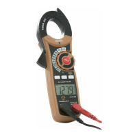
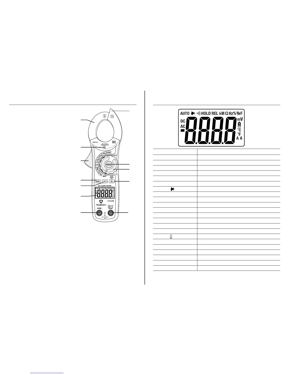
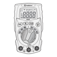
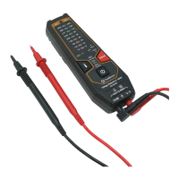
Meter Description
1. Current clamp
2. Non-contact AC voltage indicator light
3. Clamp trigger
4. Data Hold button
5. Rotary function switch
6. MODE select button
7. Frequency/Duty Cycle button
8. Relative button
9. LCD display
10. COM input jack
11. V, Ω, CAP, Temp, Hz input jack
12. Non-contact voltage detector
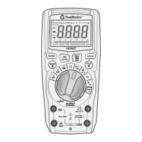
1.
2.
3.
6.
7.
10.
9.
12.
4.
5.
8.
11.
MODE BUTTON
To select DC/AC volts and
Ohm/Diode/Continuity
HOLD BUTTON
To freeze the reading on the LCD display, press the HOLD button.
The HOLD icon will be displayed on the LCD. Press the HOLD button again
to return to normal operation.
REL BUTTON
For Capacitance Zero & Offset adjustment.
Symbols Used on LCD Display
6
V Volts
A Amps
AC Alternating current
DC Direct current
- Minus sign
Ω Ohms
•))) Continuity
Diode test
F Farads (capacitance)
Hz Hertz (frequency)
% Percent (duty cycle)
ºF Degrees Fahrenheit
ºC Degrees Centigrade
AUTO Autoranging
REL Relative
HOLD Display hold
Battery status
n nano (10
-9
)
µ micro (10
-6
)
m milli (10
-3
)
k kilo (10
3
)
M mega (10
6
)
OL Overload