9
Diode Test
Continuity Test
Never test diodes in a live circuit.
WARNING:
1. Set the rotary function switch to the Ω •))) position.
2. Insert the black test lead into the negative COM
input jack and the red test lead into the positive
Ω input jack.
3. Press the button until the “ ”symbol
appears on the LCD display.
4. Touch the test probes to the diode under test.
5. Forward voltage will indicate 0.4V to 0.7V on
the LCD display. Reverse voltage
will indicate “OL”. Shorted devices
will indicate near 0V and an open
device will indicate “OL” in both
polarities.
Never test continuity on a live circuit.
WARNING:
1. Set the rotary function switch to the Ω •))) position.
2. Insert the black test lead into the negative COM input jack and the red test
lead into the positive Ω input jack.
3. Press the button until the “•))) ” symbol
appears on the LCD display.
4. Touch the test lead probes to the device or wire
being tested.
5. A tone will sound if the resistance is approximately
30 ohms or less.
Operation cont.
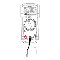
Red Black Black Red
Probe Probe Probe Probe
Forward test Reverse test
10
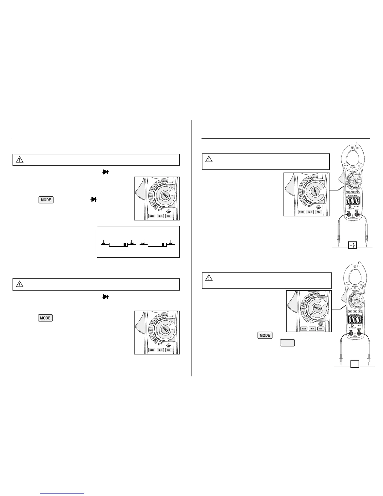
Capacitance Measurements
Safely discharge capacitors
before taking capacitance measurements.
WARNING:
Operation cont.
1. Set the rotary function switch to
the CAP position.
2. Insert the black test lead into the
negative COM input jack. Insert the
red test lead into the positive CAP
input jack.
3. Touch the test leads to the capacitor
to be tested.
4. Read the capacitance value on the LCD display.
Large capacitors may take up to 1 minute to get a
stable reading.
Frequency or % Duty Cycle Measurements
Observe all safety precautions
when working on live voltages.
WARNING:
1. Set the rotary function switch to
the VDC/AC, Hz position.
2. Insert the black test lead into the
negative COM input jack and the
red test lead into the positive V
input jack.
3. Select AC volts with the button.
4. Select Hz or % duty cycle with the
Hz/% button.
5. Touch the test probe tips to the circuit under test.
6. Read the frequency or duty cycle on the LCD display.
Hz
 Loading...