32
SETUP MENU
The SETUP menu has 3 submenus: UNIT SETTINGS,
FAN SETTINGS, and TIMERS.
1. UNIT SETTINGS
The UNIT SETTINGS menu consists of 8 submenus:
MODEL, UNIT SIZE, UNIT TYPE, Reversing valve [RE-
VERSE VALVE] settings, Secondary Hot Water Coil [SEC
HW COIL], Auxiliary Relay 1[AUX 1], [FAN] CONSTANT
SPEED or CONSTANT PRESSURE driven operation, and
anti-frost temperature setting [AFST TEMP].For units with
firmware versions 1.5 or higher, there is a 9th submenu
option. [AFST DELAY].
1.1 MODEL: This menu will allow you to select the
model of the unit: ESP or WCSP.
1.2 UNIT SIZE: There are 6 unit sizes options:
2430H/V, 3642H/V, and 4860H/V.
1.3 UNIT TYPE: An ESP model can be configured
as refrigerant heat pump by selecting [HP], or as
cooling only mode available [AC] unit. A WCSP
mode can be configured as a Reverse cycle
chiller [RCC], or as a cooling only [AC] unit or as
a heating only mode [HEAT] unit.
Note: These selections should only be changed by a
qualified installer and should be verified for the installation.
Note: The unit model, and size will be configured
specific to the purchased unit from the factory.
For ESP units:
For WCSP units:
1.4 REVERSE VALVE: The Reversing Valve
[REVERSE VALVE] can be set to O [energized in
cooling] or B [energized in heating]
1.5 SEC HW COIL: The Secondary Hot Water Coil
menu [SEC HW COIL] allows you to add a
secondary heating water coil as an optional item.
1.6 AUX 1: The Auxiliary 1 Relay [AUX 1] can be
set to close its contacts only during a heating
call, only during a cooling call only or on both
heating and cooling calls.
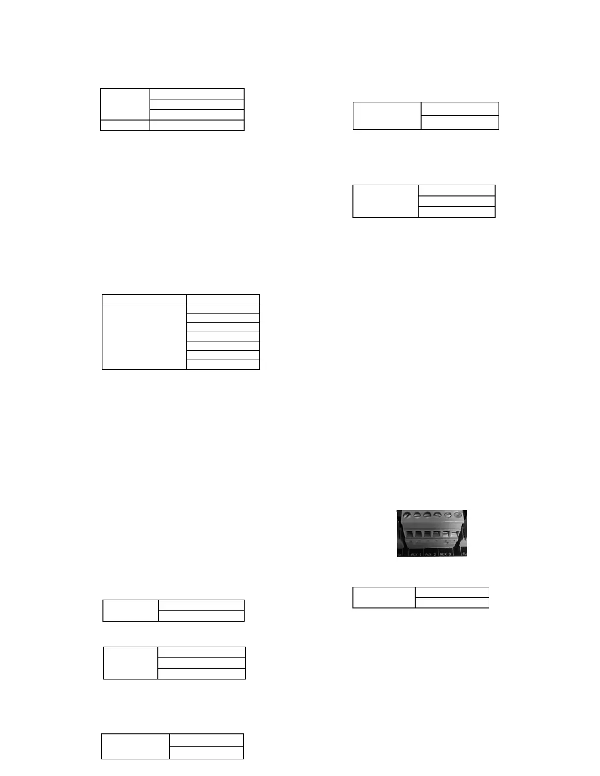
AUX 1, 2, 3: In units equipped with firmware 1.6
or higher, the auxiliary relays (AUX 1, 2, 3) can
be set to close its contacts during a heating (heat)
call only, cooling call (cool), heating and cooling
call (Heat-Cool), a fan only call (G) or fan only,
heating and cooling calls (GHC). For units equipped
with firmware 1.5 or lower, the Auxiliary 1 relay
(AUX 1) can be set to close on heating only
(heat), cooling only (cool) or heating and cooling
(heat-cool). The Aux2 terminal will always be
energized during any cooling call and the Aux3
terminal will always be energized in a heating
call. In a unit that is commissioned for WCSP;
The Aux2 and 3 terminals are designed to work
with the Spacepak Air to Water Heat pump family
of products. Aux2 will be wired to the “remote
on/off” terminals located in the air to water heat
pump electrical compartment and Aux3 will be
wired to the “Heat/Cool” terminals of the air to
water heat pump. Refer to your specific air to
water heat pump for the exact terminal numbers,
wiring locations and follow the recommended
piping practices detailed in the manual for the
specific air to water heat pump.
1.7 Fan Speed: The fan can be run at either a
constant speed or a constant static pressure.
When Constant Speed is selected a different speed %
can be selected for each input. (Y1, Y2, W1, W2, or
G). The fan will run at the set speed % for the active
input. This setting can be from 5% - 100%
When Constant Pressure is selected a different static
pressure setpoint can be selected for each input. (Y1,
Y2, W1, W2 or G). The fan will vary its speed to
maintain the static pressure target of the active input.
See section 2, FAN SETTINGS, for information on
setting the speed % or static pressure setpoints.