38
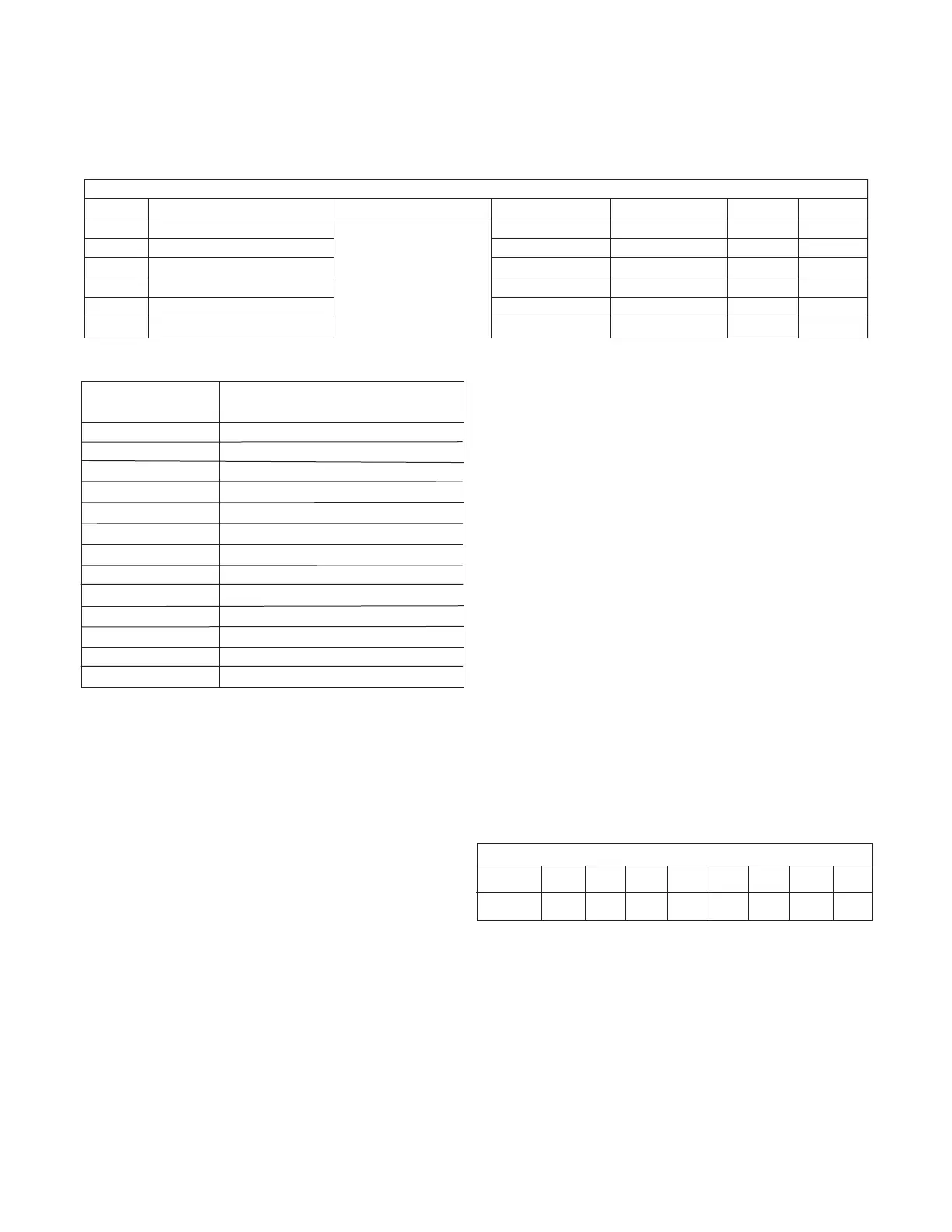
FIGURE 3.2
*For a room with more than two (2) terminals, combinations of
the above may be used to achieve the desired fractional number.
2" SUPPLY TUBING LENGTH ADJUSTMENT FACTOR CHART
RUN 6' 8' 10' 12' 15' 20' 25' 30'
FACTOR 1.18 1.14 1.11 1.06 1.0 .9 .8 .66
DESIRED NUMBER
OF TERMINALS*
.5
.65
.85
1.00
1.15
1.30
1.50
1.65
1.70
1.80
1.85
1.95
2.00
TERMINAL - ORIFICE
COMBINATION
(1) .5
(1) .35
(1) .15
(1)
(1) .5 + (1) .35
(2) .35
(1) .35 + (1) .15 or (1) + (1) .5 or (3) .5
(1) + (1) .35 or (2) .5 + (1) .35
(2) .15
(2) .35 + (1) .5
(1) + (1) .15
(3) .35
(2)
C. Supply Tubing Length: An outlet with a supply tubing
length of 15 feet is considered one, fully opened outlet.
For other lengths refer to Figure 3.3 for adjustment
factors.
FIGURE 3.3
A. Room Terminators (Outlets): Based on the equipment
selected, determine the recommended number of fully
open outlets from Figure 3.1.
FIGURE 3.1
FACTORS AFFECTING THE BALANCE OF THE SYSTEM
1. The minimum or recommended number of outlets means
fully open outlets. Any outlet having an orifice would be
only a percentage of an outlet.
2. For systems with average supply tubing lengths of 15
feet or less, use column A. For systems with supply
tubing lengths greater than 15 feet, use column B.
NOTICE: The number of outlets and average length of the
supply tubing has a significant effect on the overall sys-
tem performance. It is highly recommended that the ad-
justment factors outlined in the SpacePak Application
Manual are accounted for prior to any installation.
B. Orifice Combinations: Should orifices be required to
balance the system (installed at plenum take-off),
refer to the combinations listed in Figure 3.2.
RECOMMENDED OUTLETS AND CFM'S
Model Size Nominal Tonnage (outdoor unit) Recommended CFM/outlet Number of outlets A Number of outlets B Total CFM A Total CFM B
2430 2
33
12 14 396 462
2430 2.5 15 18 495 594
3642 3 18 21 594 693
3642 3.5 21 25 693 825
4860 4 26 28 858 924
4860 5 30 35 990 1155