35
FAULTS AND WARNINGS:
The integrated control board is equipped to identify com-
mon faults and potential warnings during the operation
of the air handlers. See below table for troubleshooting
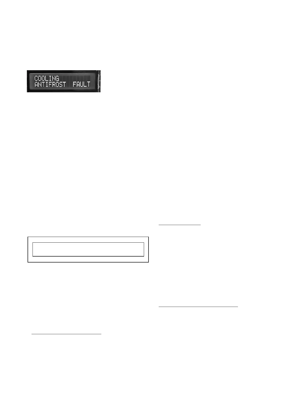
details on faults and warnings. When a fault or warning
is present the screen will present the associated error
on the screen on Line 2 as shown in the example below.
Faults and Warnings Explained (for troubleshooting
refer to troubleshooting table)
FLOAT SW FAULT- The primary drain pan float switch
has faulted. A call to the outdoor unit will not be al-
lowed. This is a hard lockout that requires a power
cycle to reset.
ANTIFROST SW FAULT- The anti-frost sensor has
measured a temperature lower than the setpoint (de-
fault of 34°F can be used adjusted by using the menu
tree above). For units with firmware 1.4 or less, the unit
will auto reset once the temperature of the coil is 6°F
above the setpoint. For units with firmware 1.5 or
greater, the unit will reset after the coil 1 temperature is
20° above set point AND a 2 minute time delay to pre-
vent short cycling of the outdoor unit. Please note that
the time delay and temp differential are adjustable in
the menu tree.
LOW PRESS FAULT- The pressure transducer (located
on the control board) is reading less than .1” when the
fan is running. During this fault, the unit will not display
a calculated CFM or a static pressure reading. The
blower will continue to run and the unit operation will
change (automatically) from constant pressure to con-
stant speed.
TRANSDUCER FAULT- The control board has regis-
tered that the pressure transducer has failed on the
control board or the calibration has failed. The blower
will continue to run during this fault.
OPEN COIL 1- The control board has recognized an
open circuit on the primary coil (coil 1) terminal. When a
unit has this warning, the display screen will flash the
warning. The fan will not run until the warning is re-
solved or after a 2 minute delay.
ERRORS:
Configuration - Wiring Errors.
The J+ Control is able to recognize wiring and configura-
tion errors. If conflicting inputs are received, the control will
always prioritize heating over cooling an error message
will be displayed, but the unit will continue to operate.
Based on the unit configuration the following errors can
be recognized.
Unit Configuration: HP/ RCC
RV = O [REVERSE VALVE ON COOLING]
For Heating Mode: Expected inputs: Y’s, Y’s+W’s.
For Cooling Mode: Expected inputs: Y’s+OB.
RV = B [REVERSE VALVE ON HEATING]
For Heating Mode: Expected inputs: Y’s+OB, Y’s+OB
+W’s
For Cooling Mode: Expected inputs: Y’s.
Detected inputs; W’s+OB or OB
ERRORS:
Error 1: Unexpected OB, Configuration error.
Wiring error.
Error 2: Unexpected W’s+OB, Configuration error.
Wiring error.
Unit Configuration: COOL ONLY FOR BOTH MODELS
Expected inputs: Y’s or W’s.
Detected input: OB
ERRORS:
Error 1: Unexpected OB, Configuration error. Wiring
error.
Error 2: Unexpected W’s + OB, Configuration error.
Wiring error.
Error 3: Unexpected Y’s + OB, Configuration error.
Wiring error.
Error 4: Unexpected Y’s + W’s, Configuration error.
Wiring error.
Unit Configuration: HEAT ONLY FOR WCS ONLY
Expected inputs: W’s.
Detected inputs; Y’s, Y’s+OB, or OB
ERRORS:
Error 1: Unexpected OB, Configuration error. Wiring
error.
Error 3: Unexpected Y’S + OB, Configuration error.
Wiring error
Error 5: Unexpected Y’S, Configuration error.
Wiring error.