Seaich Corporation, LLC. All rights reserved. www.seaich.com
|
Spacerails, LLC. www.spacerails.com Page 9
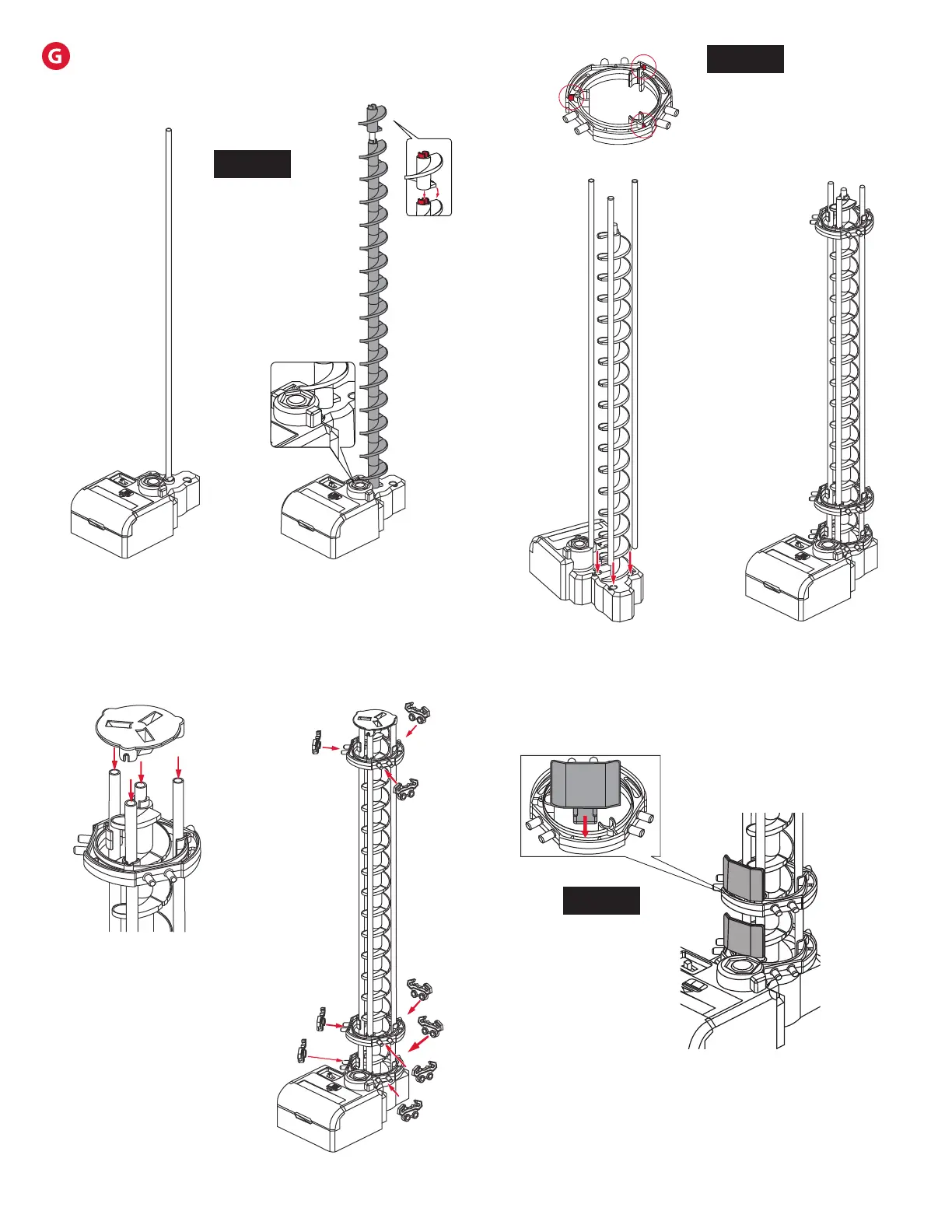
Step 3: Once the Corkscrew
is built, attach three support
shafts to the Power Box.
Step 1: Place a 391 mm
Shaft in the white hole on
the Power Box.
ELEVATOR ASSEMBLY
Illustrations are approximately 33% of actual size.
Step 2: Connect Elevator
Helix pieces together with
the male part facing up to
ll the shaft.
Step 4: Slide each Elevator
Ring into position on the
support shafts right-side up.
NOTE:
The Marble may
fall out of the
elevator if it
enters too fast.
Step 7: Insert three Elevator Guards each
in the bottom two Elevator Rings.
Step 5: Place the Elevator
Cover onto the top of the
elevator assembly.
NOTE:
Elevator Rings are
right-side up when tabs in
red are on the top.
NOTE:
Install the rst
Elevator Helix
piece male side up
and rotate it until
it slides in place
and engages with
driver at the base
of Power Box.
Step 6: Attach Rail Clips
to each Elevator Ring
as shown.
347 mm
32 mm