www.spalusa.com
5
Operation
The FAN-PWM is equipped with 2 LED’s: a ‘STAT’ LED and a ‘FAN’ LED.
‘STAT’ LED will be lit when the unit is powered on, system checks are OK, and
the fans are not running.
The 3 color ‘FAN’ LED indicates when the fan output is active, and is also used
during programming. Each color represents the following: AMBER for tempera-
tures above LOW, RED for temperatures above HIGH, and GREEN when the
A/C input has been activated.
When the Low temperature setting is reached, the ‘FAN’ LED will light AMBER,
and the fan will run at 50% or ½ speed. The fan will then gradually increase
in speed as the engine temperature rises. If the high temperature setting is
reached, the ‘FAN’ LED will light RED, and the fan will now be running at full
speed. (continued next page)
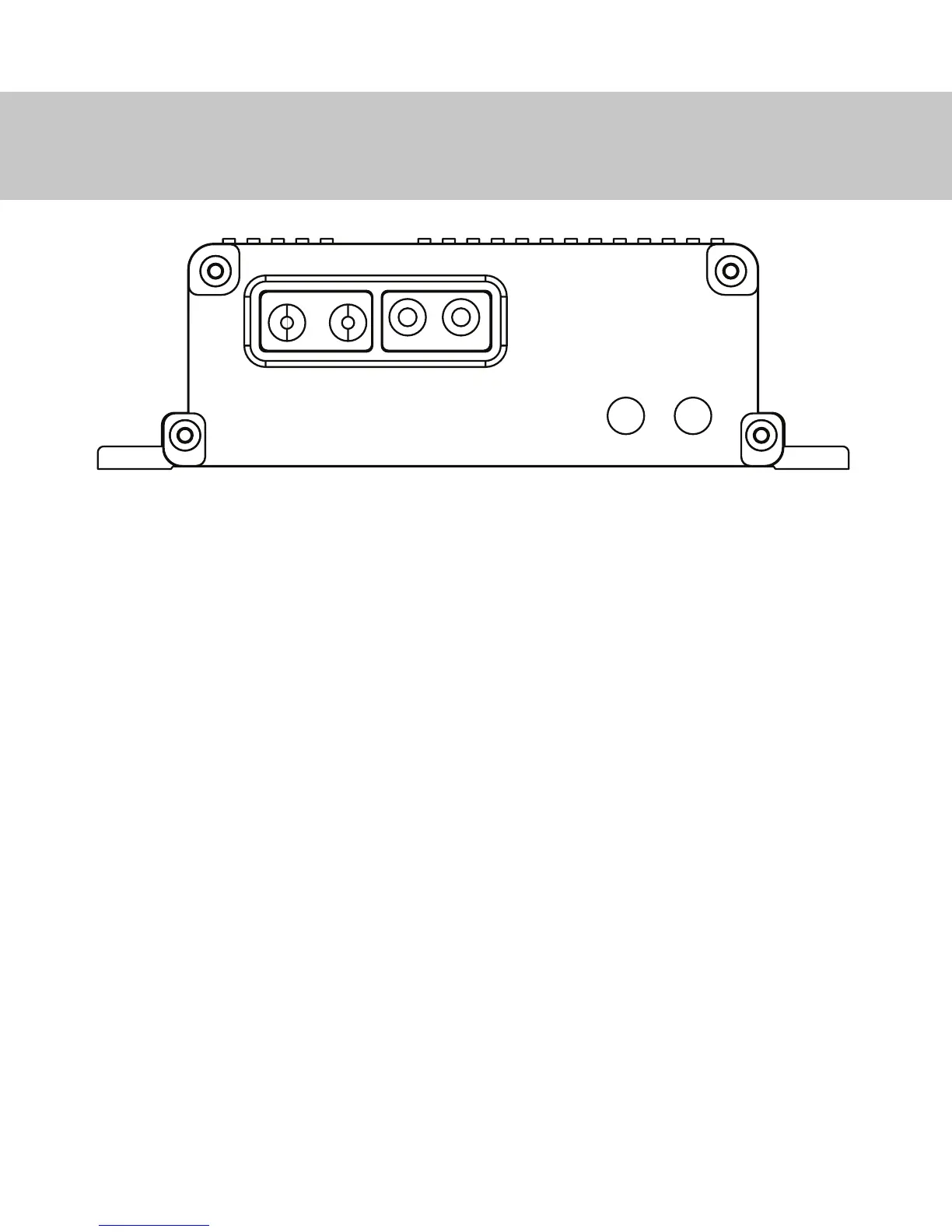
Front View of PWM
ENTR PRG STAT FAN
 Loading...