V.2005 Page | 2
ELECTRICAL INSTALLATION
• All electrical connections must be performed by a licensed electrician and must conform to all
national, state and local electrical codes in effect at the time of installation.
• The appliance should be supplied through a residual current device (RCD) having a rated residual
operating current not exceeding 30mA.
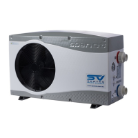
• The supply line should be a dedicated power circuit. The installer should consider the sum total load
of all devices connected to the SV Mini controller when determining the size of the power circuit and
install an appropriately sized circuit breaker to suit. Ensure circuit breaker is rated for motor start
up currents. Maximum rated power circuit is 25A.
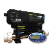
• Heater load shedding is set by default, so that the heater load sheds and turns off as soon as any
device other than Pump 1 is switched on. The installer should consider this when determining the
size of the power circuit required. Heater load shedding can be adjusted if desired. Refer to “Heater
Load Shedding” section on page 18 of this manual for further information.
Electrical Specifications
Wiring Diagram (Mini 1)
Output Ratings
Circ / 2-spd or 1-spd Pump