MKP-1.1 FEATURES
The MZC-66 System can be controlled using SpeakerCraft EZ-
Pads, IMKPs and MODE 3.1s. Keypad configurations vary from
system to system and some parts may need to be ordered
separately.
Each keypad comes with a set of factory installed “default but-
tons” plus a good variety of loose buttons packed with them.
The default buttons can be easily changed to meet the needs
of the installation. For more information on changing keycaps,
see: MZC-66 Hardware Installation Instructions. The MKP-1.1
shown reflects the Source configuration of the EZ Tools MZC-66
Default Project.
A Function Module (FKP-1.0) and Numeric Module (NKP-1.0) are
available options for additional control capability, however, a
MKP-1.1 or MKP-1.0 Master Keypad is required for each zone
as the NKP-1.0 and FKP-1.0 will not function on their own. See:
MZC-66 Hardware Installation Instructions for additional infor-
mation.
4
A
B
C
D
E
F
0
1
2
3
4
5
6
7
8
9
iPOD1
CD
DVD SAT
CBL
AUX
BASS TREB
MUTE
PWR
ADDRESS
KEYPAD EXPANSION
MKP-1.1
J-Box EZ-Pad w/IRC
-Master-
SpeakerCraft
+RELAY
-RELAY
+12V
IR I/O
GND
485 A
485 B
MUTE
iPOD1
CD
DVD SAT
CBL AUX
BASS TREB
PWR
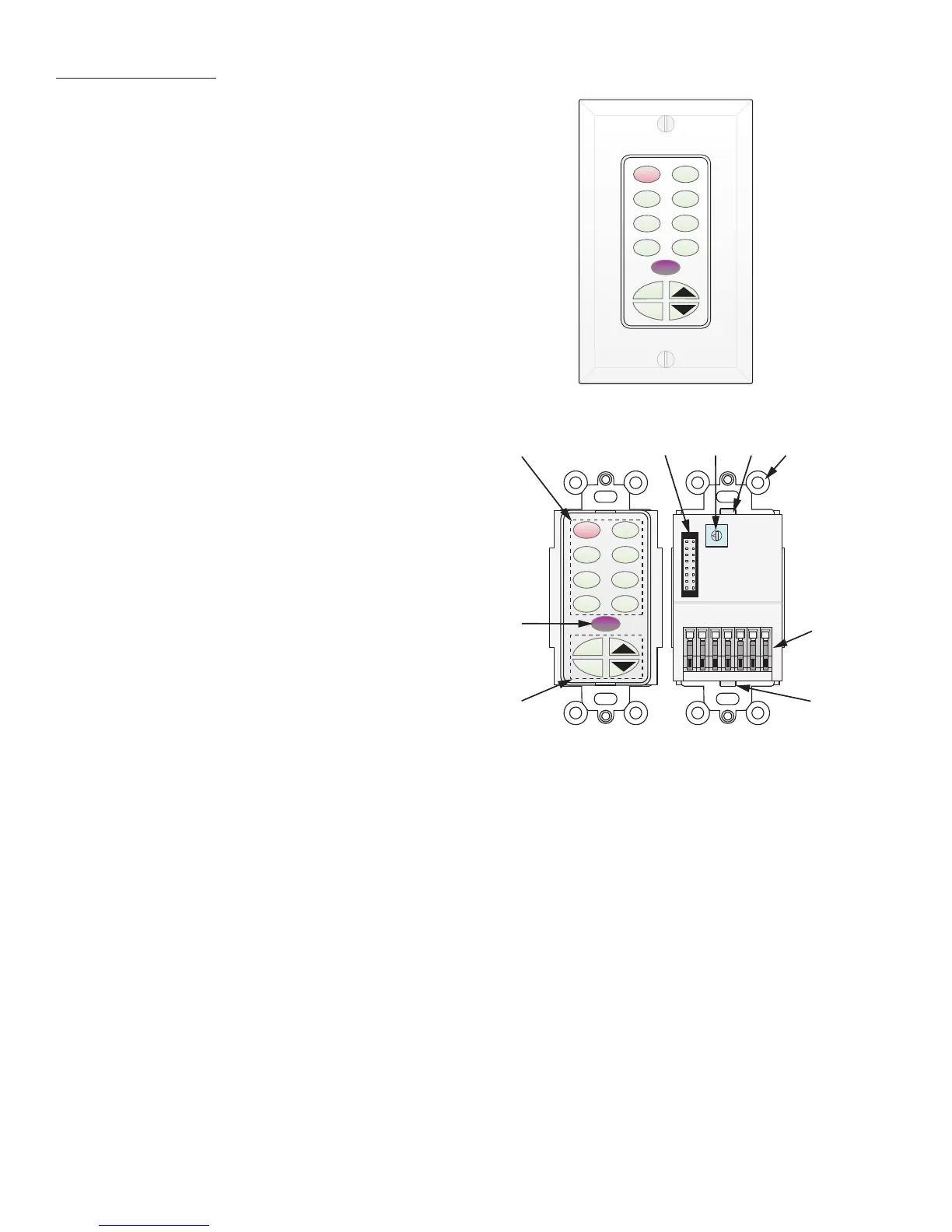
1. MKP-1.1 Source/Function Buttons – When used with MZC-66,
up to s
ix of this set of eight buttons may be programmed
as Source Selects for the MZC-66. Any mix of source/
transport/function buttons is allowed as long as one of the
eight is designated as a Source Button. All buttons have an
optional green backlight, configurable in EZ Tools. Default
timeout is 60 sec. When a Source Button is pressed, it turns
to a low-level red color to show that it is the active source
and the system is on.
2.
KEYPAD EXPANSION Terminal – This 16-pin header terminal
is used to inter-connect the NKP-1.0 and FKP-1.0 modules
for numeric and function key expansion as needed. A
ribbon cable is packed with each NKP-1.0 and FKP-1.0 for
making these connections.
3.
ADDRESS Switch – An unique hex address must be set for
each master keypad when connected on a common bus
within a single zone. Unique addresses are not required
zone-to-zone. (One keypad per zone.) It provides up to 16
addresses (0 to F).
4. Snap Tabs – These tabs hold the decorator style insert panel to the metal mounting plate and are easily released for custom
changing of the buttons.
5.
Mounting Plate – Standard plate allows the keypad module to be attached to standard in-wall J-Boxes using the 2 screws
provided. Allows attachment of standard decorator type cover plates (also screw-less snap-on plates).
6.
EZ-Connect Terminals – These spring-loaded terminals accept wire sizes 14 to 28 AWG for connection of the following:
+Relay/–Relay – For connection of an optional EPR-1.0 EZ-Pad Relay Speaker Muting Module. See MZC-66 Hardware
Installation Instructions for additional information.
+12V DC –
Powers the Keypad, including the internal IR Receiver. Includes reverse voltage protection.
IR/IO (Data) –
Sends IR control signals for control of system components.
GND –
Return for Power, IR signal and Data
485 A/485 B –
Balanced, bi-directional system communications data.
7. Function Buttons –
These lower 4 buttons (5 buttons in the case of the MKP-1.0) can be programmed for any function except
source select.
8.
IR Receiver Lens – EZ-Pad version MKP-1.1 includes SpeakerCraft’s exclusive ANS IR Receiver, built-in. The IR Receiver allows use
of a handheld remote for control of system components.
1
2 3 4 5
6
4
7
8
MKP-1.1 Master Keypad
Rear View
MKP-1.1
With Trim Plate (Not Included)

 Loading...