INSTALLATION INSTRUCTIONS (continued)
5. PREPARE THE LOCATION PRIOR TO WIRING:
FLUSH MOUNT: Use the template provided to position and mark the cutout and the four
mounting holes. Make the cutout using a keyhole or saber saw. Start by drilling holes
in the corners, and then saw between the holes.
WALL MOUNT: Mount the knockout box to the wall using suitable fasteners.
6. SELECT WIRE:
WIRE TYPE: - When possible, use stranded wire instead of solid wire. Stranded wire
does not fatigue and cause loose connections over time as easily as solid wire. Use
red wire for (+) and black for (–).
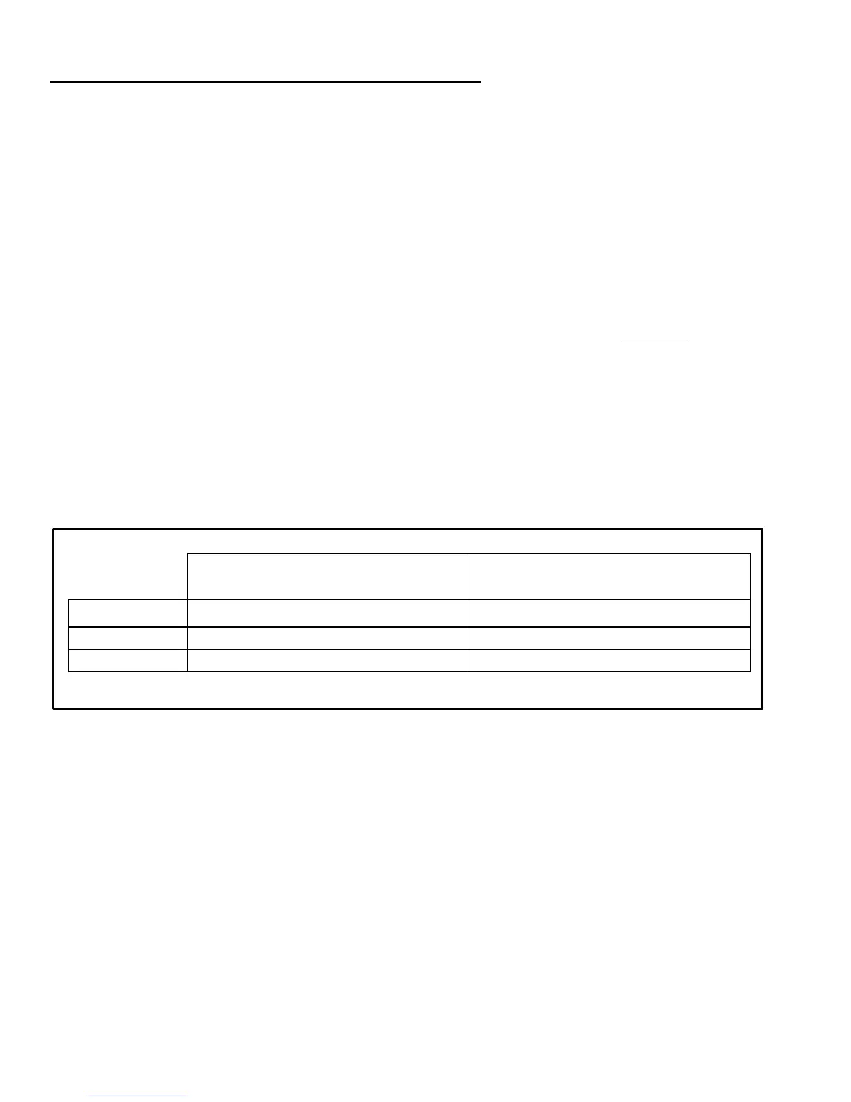
WIRE SIZE: - Refer to the “WIRE SIZE” chart below to determine the minimum size wire
needed for each connection. Note that the bigger the wire, the lower the AWG. When
using large stranded wire, you may need to divide the ends into two groups and
straddle the screw on the terminal block.
MARK/15: accepts one wire at 8 AWG (stranded) or two wires at 10 AWG.
MARK/20: accepts one wire at 6 AWG (stranded) or two wires at 8 AWG.
Large Wires: To connect large wire to the MARK/(15,20), use crimp connectors or
connect the larger wire to a short, thinner wire using a wire nut (solder these
connections).
Wire Size: Minimum wire gauge (AWG) - (based on maximum current)
Model
MARK/15 10 8 6* 4* 14 12 10 8
MARK/20 10 8 6 4* 12 10 8 6
* Wire gauge larger than unit can accept directly. See WIRE SIZE / Large Wires above.
7. COMPLETE THE INSTALLATION OF PANELS, BATTERY AND LOAD: - Follow the
manufacturer's instructions for mounting and wiring the solar panel, batteries and the
load. Install with the correct series-parallel configuration to insure proper system
voltage and current.
8. REMOVE POWER FROM BATTERY / PANELS (if needed): - Before running the
wires to the MARK/(15,20), be sure that power is disconnected from the batteries and
panels.
9. RUN SYSTEM WIRING: - After disconnecting the power sources, run the wires from
the battery and solar panel to the location selected for the controller.
WALL MOUNT: Run the array and battery wires into the box through the knockouts,
using a 1/2 inch Romex cable clamp for strain relief.
Distance round trip (feet / meter)
Solar Array Connection
Distance round trip (feet / meter)