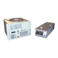
Table 4-10 D-Series power supply bottom rear panel connections
Connection Description
Fiber-optic cables (2 or 4) Delivers optical pump power from the laser diodes to the Pulseo laser head. The fiber-optic
cables on the D-Series power supply are not permanently attached to the diode modules inside
the power supply and can be replaced in the field by a qualified service engineer if damaged.
Water hose/coolant
attachments
Connection for the hose that brings coolant from the Pulseo laser head and the hose that
returns heated coolant to the chiller.
Coolant must flow from the chiller to the laser head before flowing to the D-Series power supply.
Fuses (F1
and F2) Slow-blow devices rated for 10 A at 250 V. To change a fuse, first turn off the power supply and
disconnect the power cord. Use a flat-blade screwdriver to turn the slotted fuse cap
counterclockwise, then pull the cap off and replace the fuse with a similar fuse. Refer to
Table 3-2 for fuse size and type.
The power supply AC circuit is double-pole, neutral fused. Failure to unplug the unit during fuse
replacement can present a shock hazard.
AC power cord connector Attachment for one of two power cords provided with the unit. Connect the appropriate cord to
a 100 to 240 VAC single phase power source. The connector is supplied by Interpower, P/N
8303-0400.
Ground connector
(10-32 stud)
Connection for a suitable grounding strap. The laser head is connected to ground through the
LASER HEAD control cable. Although the unit implements a ground connection in the
C20-style power inlet, an additional strap should be connected to the marked ground stud on
the rear of the power supply. Verify that the ground is secured tightly before operating the
equipment.
This unit is provided with a grounded appliance inlet. The AC power source outlet must have a
grounded connection. The ground should be verified prior to use.
Clear access must be provided for the user to disable primary power at the AC power switch on
the front of the power supply (see Figure 4-4). In the event of a hazard (fire, electrical shock,
undesired optical emission, etc.), use this switch to disconnect primary mains power to the unit.
The unit must be mounted so that clear access is provided to this switch.
Opto-Isolated Connections of the LASER CONTROL Interface
Controls, Indicators, and Connections 4-13
NOTE: Each fiber port on the laser head is numbered (see Figure 4-2) to match the labeling
on the fiber cable. Be sure to match each cable to the corresponding port for proper
system operation.
 Loading...