2 Setup, Connection, and Cabling
12 Epoch 25 L1/L2 GPS System User Guide
2.1 Parts of the base receiver
The operating controls, serial ports, and connectors are on the bottom panel of the
base receiver. (The "bottom" panel is the panel underneath the receiver.)
• The power button controls the receiver’s power on or off functions.
• Three indicator LEDs show the status of power, satellite tracking, and radio
reception. See also LED behavior, page 22.
21.1 Ports and connectors
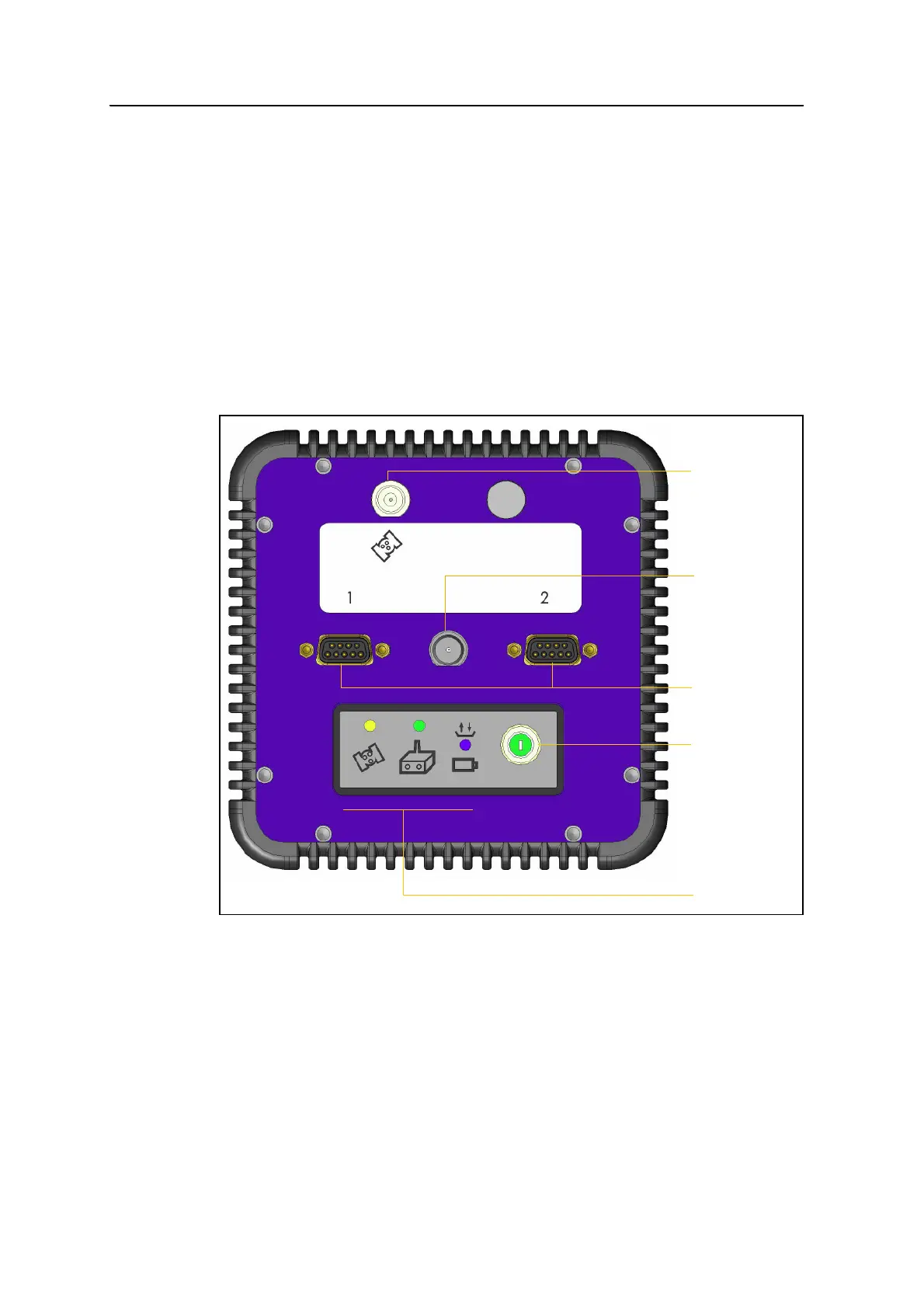
Figure 2.1 shows the two serial ports, one TNC radio antenna connector, and the
5/8-11 threaded insert.
Figure 2.1 Ports and connectors on the base receiver
• Port 1 is a DE-9 male connector that allows for full 9-pin RS-232
communications and external power input.
• Port 2 is a DE-9 male connector that allows for full 9-pin RS-232
communications and external power input as well as power output. For more
information, see Chapter 6, Default Settings and Chapter 7, Cables and
Connectors.
• Use the TNC connector to connect a GPS antenna to an L1/L2 Epoch receiver.
Serial ports
TNC connector
Indicator LEDs
Power button
5/8-11
threaded
insert
 Loading...