INSTALLATIONS
12 MB720 User’s Manual
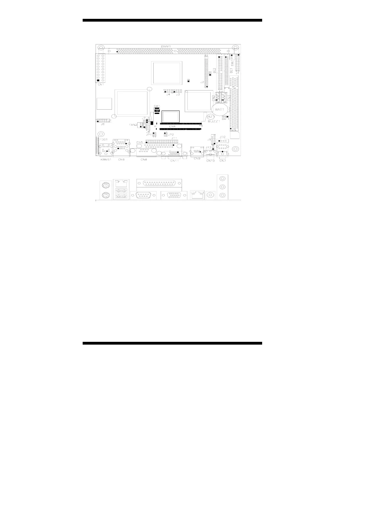
Connector Locations on MB720
Connectors on MB720..............................................................................................................Page
FDD1: Floppy Drive Connector...................................................................................................13
IDE1, IDE2: Secondary and Primary IDE Connectors ................................................................13
FAN1: System Fan Power Connector ..........................................................................................14
FAN2: CPU Fan Power Connector ..............................................................................................14
CN1: ATX Power Supply Connector...........................................................................................15
CN2, CN3: Serial ATA (SATA) Connectors...............................................................................15
CN4: Mini PCI Connector............................................................................................................15
CN5: Parallel Port Connector.......................................................................................................15
CN6: RJ45 and 2 USB Ports ........................................................................................................16
CN7: Line Out, Line In, Mic Connector ......................................................................................16
CN8: COM1 Serial Port ...............................................................................................................16
CN9: RJ45 Connector for LAN1 (10/100)...................................................................................16
CN10, J12: TV out Connector (RCA Jack/CN10 and 3-pin Header/J12)...................................16
CN11: VGA CRT connector ........................................................................................................17
J1: System Function Connector....................................................................................................17
J2: LVDS Panel Interface (used with ID380 Card, not in A1 version) .......................................19
J3, J4: USB Connector (USB3/USB4, USB5/USB6) ..................................................................19
J7: IrDA Connector ......................................................................................................................19
J8: Digital 4-in 4-out I/O Connector ............................................................................................19
J10: CD-In Audio Connector .......................................................................................................20
J11: Serial Ports ............................................................................................................................20
PS2-KBMS1: PS/2 Keyboard and Mouse Connectors ................................................................20