3 Control Panel
The control panel of each PSR Series spectroradiometer contains the controls and displays that are
required for the stand-alone operation of the instrument.
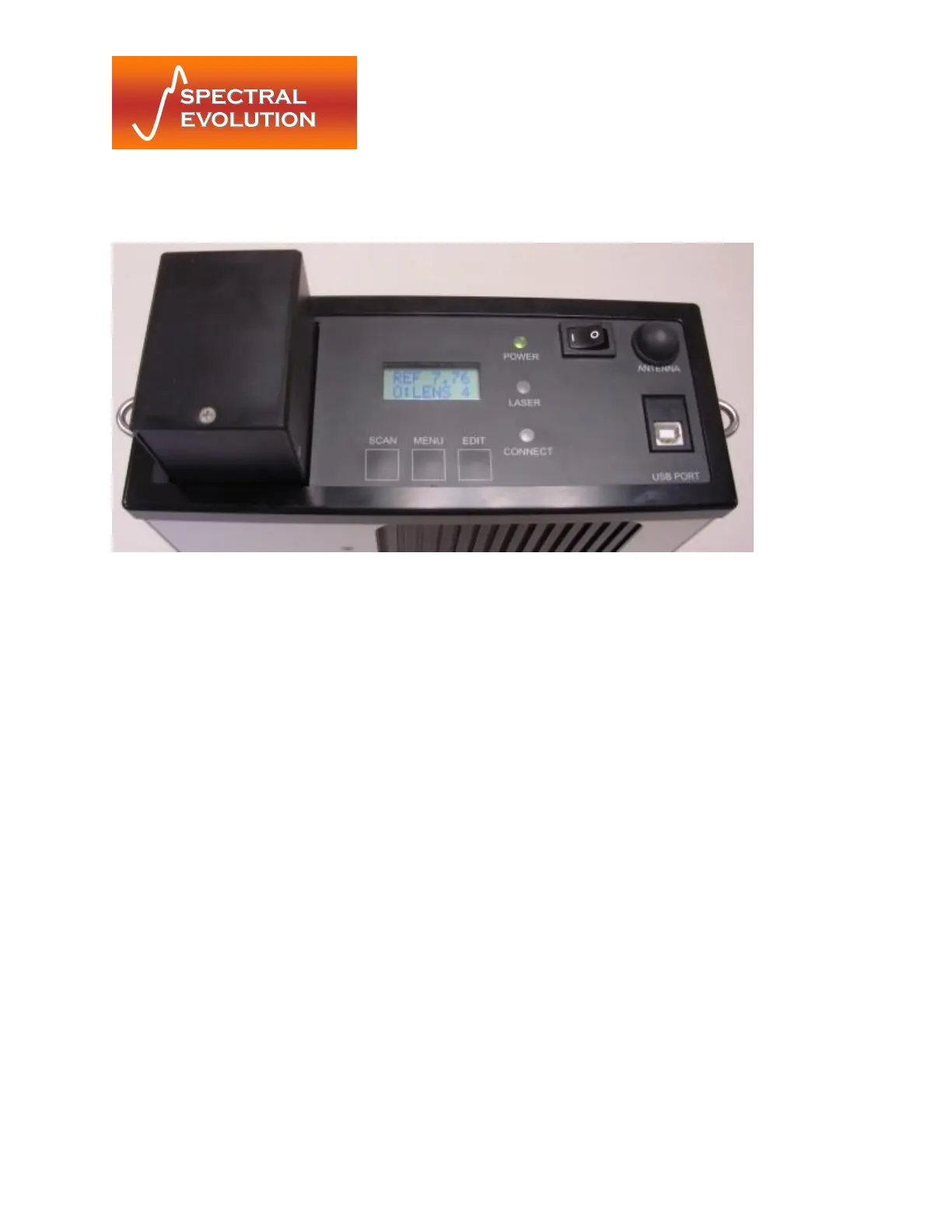
Figure 5: Control Panel Detail
3.1 Indicators
The Control Panel has 3 LED status indicators.
Power LED The power indicator is illuminated when the power is on.
Laser LED The laser indicator is illuminated when the laser is on.
Connect LED The connect indicator is illuminated when no Bluetooth communication link has
been established.
3.2 Switches
3.2.1 Power Switch
The power switch provides on/off control of the unit.
3.2.2 Membrane Switches
The three (3) membrane push button switches provide control of the unit during standalone
operation and the capability of modifying the unit’s operation. The functions of the switches are
detailed below.
3.2.3 Switch Function
Scan Steps through scan options (Reference/Target/Dark Scans)
Menu Steps through the menu options (Memory Scan#/Dark Scan Mode/Scan
Timer/Optic/Laser Scanning)