2.1.4 Tripod Mount
The tripod mounting plate is conveniently located enabling the spectroradiometer to be
mounted on a tripod. The mounting plate on the bottom of the instrument has a 1/4 -20
NC threaded hole that is compatible with most conventional photographic or video
tripods.
2.1.5 Serial Communications
Communications with the PSR Series are conducted using USB or Bluetooth.
USB communications require a standard cable with USB-B connector to fit the
receptacle on the control panel. The first time the host PC is connected to the
instrument, Windows® will need to install drivers for the virtual COM port functionality.
These drivers are included on the CD-ROM that was provided with your unit. Once the
drivers are loaded, the provided Windows® application software interacts with the
spectroradiometer using a virtual COM port in the same fashion as a standard RS-232
serial port (115200 baud, 8 data bits, 1 stop bit, no parity).
All PSR Series instruments are enabled for wireless communications with the
application software provided the user has installed a Bluetooth serial port on the host
PC. Depending on your Bluetooth adapter’s configuration utility, you will need to enter
an identifier for your instrument type (typically called its PIN key or pairing code) the first
time you use your instrument. This code will be “psr3500”, “psr2500” or “psr1900” as
appropriate. Your Bluetooth utility will recognize the instrument by a unique name with
the syntax “PSR-<Model#> <Serial#>.
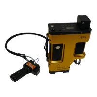
2.1.6 Front Panel
The front panel of all PSR Series spectroradiometers contains the on/off switch,
Bluetooth antenna, USB connector, battery receptacle and a control panel with
membrane switches and LCD display. See Section 3: Control Panel for more
information.
2.1.7 Laser Scan Switch
The Laser Scan switch is located on the top cover of the PSR Series
spectroradiometer. Depressing the switch actuates the sighting laser and can be
optionally configured to initiate the start of the spectral scan.
DANGER: DO NOT LOOK INTO THE LASER BEAM AT ANY TIME, INCLUDING
INSTRUMENT SETUP OR OPERATION.
For more information see Appendix A: Laser Safety.