13
Maintenance
Display and Sensor Separation:
1. Remove the probe rods from the base.
2. Flip the TDR display over.
3. Remove the 4 screws on the base using a Philips screwdriver.
4. Gently separate the display module from the base plate. Note:
The sensor cable connected in the center has limited cable length.
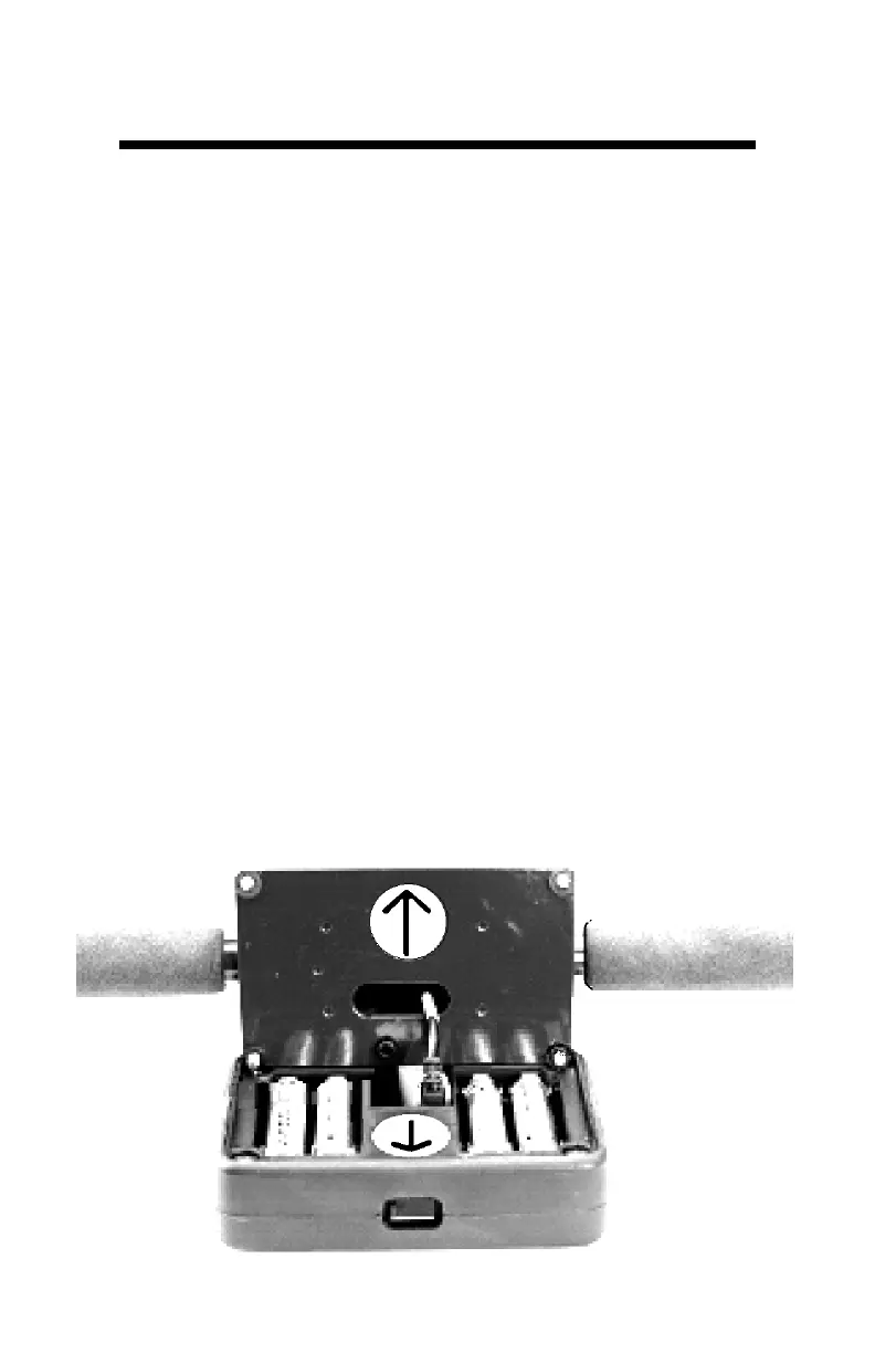
Battery Replacement:
1. Follow the steps above to access the batteries.
2. Install four new AA batteries observing correct polarity by
referencing the (+) positive and (-) negative labels.
3. Follow the display installation steps below to reinstall the
display.
Display Installation:
1. Re-connect the sensor cable to the 3.5mm connector on the
back of the display module if previously removed.
2. Insert the foam spacer back behind the sensor cable. The split
end fits around the sensor cable molding.
3. Guide the excess cable back down through the base plate.
4. Align the arrows on the base and display in the same direction.
The USB port should face the same side as the serial number
label.
5.Tighten the four mounting screws.
 Loading...