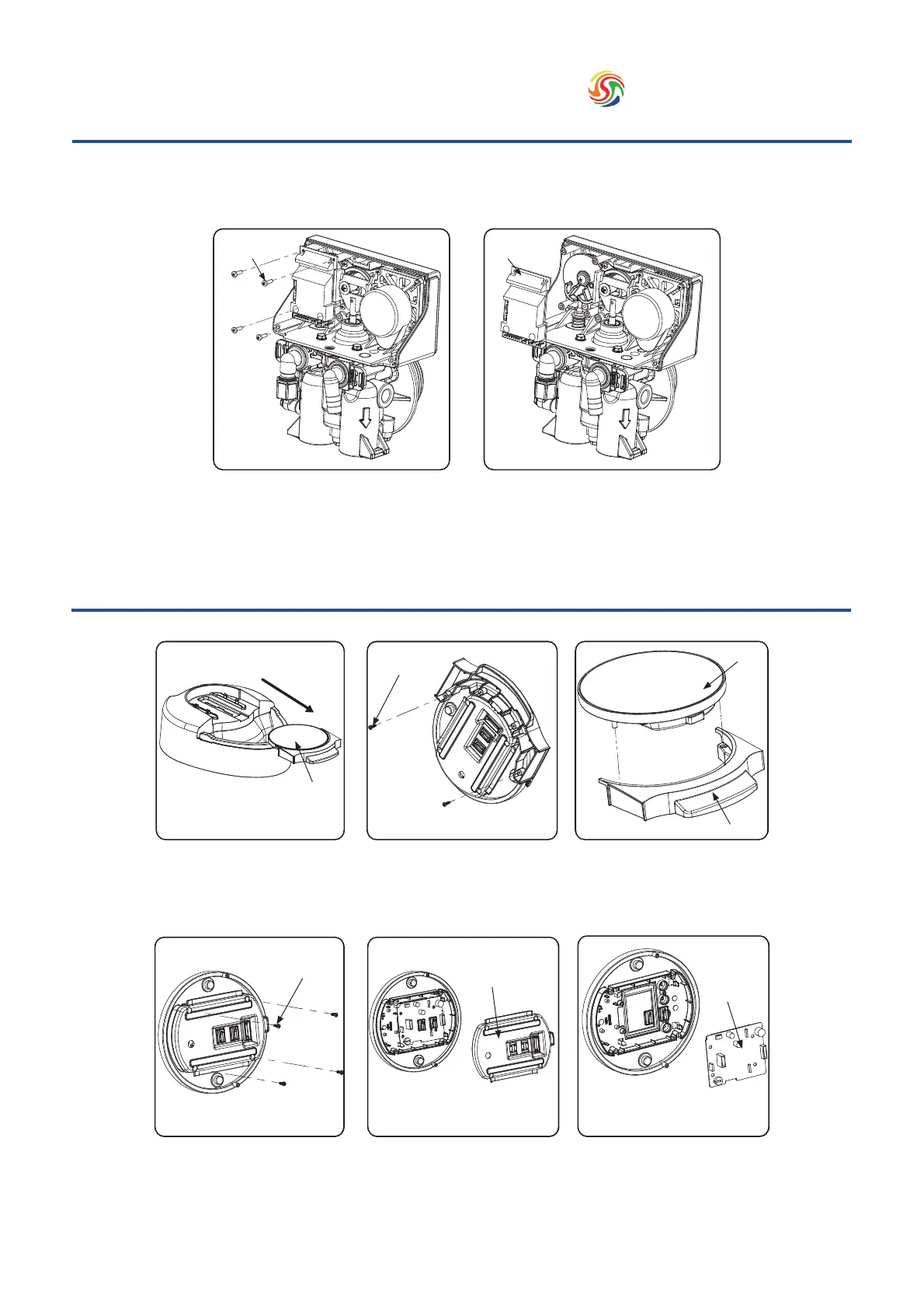
Replace Circuit Board
1. Follow steps 1 to 3 of Timer/Powerhead replacement
2. Remove all the connections of PCB
3. Remove the four scews from the PCB
4. Replace the PCB
Replace Display
1. Follow steps 1 to 6 before servicing
2. Remove the salt lid and pull out the
controller assembly
3. Remove the two screws
attached on push-pull
plate
4. Separate the panel and plate
5. Remove the four screws attached
on the back cover
6. Remove the back cover 7. Remove the display PCB
4 x screws
PCB
Contoller
Assembly
2 x screws
Panel
Push out plate
4 x screws
Back cover
Display PCB
 Loading...