Cirtix series Brushless Speed Controller manual For
“RS1/RS20602010A/100524” Page - 2 -
*If the ESC works at the status of Sensored, remove the Sensor wire, the ESC can be automatically change to the
status of Sensorless.
Sensored/Sensorless ESC’s indicated LED
Status of the function INDICATED LED Status of the LED
Low voltage of the battery Red LED Blinking
Over-heat of the ESC and motor (95℃) Orange LED Blinking
Sensored motor Red and Orange LED ON
Sensorless motor Orange LED ON
Sensorless ESC’s Indicating LED
Function Indicating LED LED Status
Low voltage of the battery Red LED Blinking
Over-heat of the ESC and motor (95℃) Orange LED Blinking
Sensorless motor Orange LED ON
Using Your New ESC
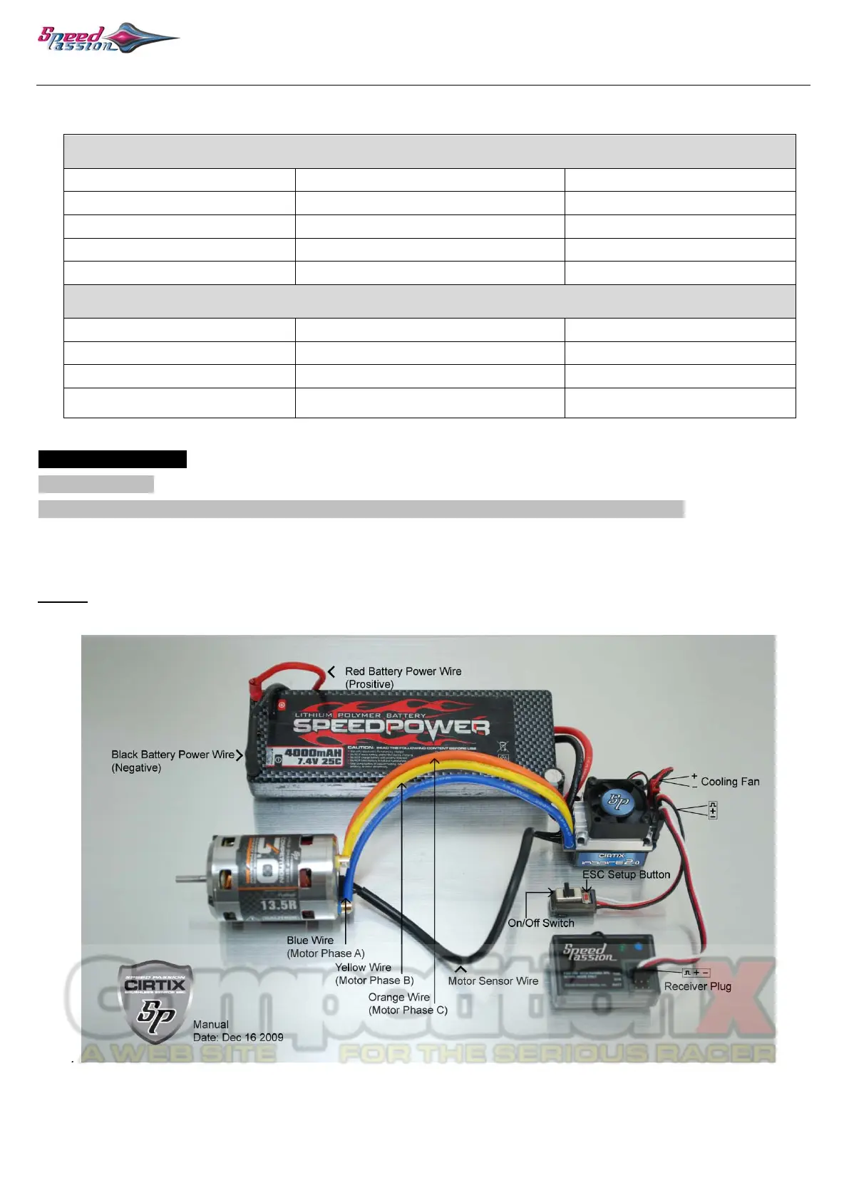
Wiring Diagram:
1. Connect the ESC, motor, receiver, battery and servo according to the following diagram
“+” and “-” wires on the ESC are connected to the battery pack, and the #A, #B and #C are connected to the motor.
The “SET” button is used for programming the ESC. The “Fan” connector is used to supply the cooling fan.
The reciever cable of the ESC (trio wires with black, red and white color) is connected to the throttle channel of the
receiver (Usually CH2).
NOTE: The Capacitor MUST be connected to the (+) and (-) of the ESC. The ESC WILL be damaged if it is operated
without the capacitor
.
a) Brushless Motor Wiring
Connected with sensored brushless motor
When using a sensored motor,it is necessary to connect the sensor cable to the “SENSOR” socket on the ESC.
The ESC can automatically identify the motor type (sensored or sensorless) by detecting the signal coming
from the SENSOR socket.
 Loading...