4 SpeedTech Lights, Inc © 2019
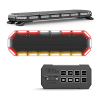
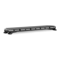
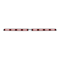
FLARE 12
HIDEAWAY
Wiring Diagram
Wire Color Function
Red*
Positive
Black*
Negative
Yellow
Flash Pattern
* Indicates a main power cable.
Wire Color Function
Green
Steady Burn Override
White
Sync
Blue
Alternating Sync Programming
NOTE: All cables except Negative and Sync contact +12 VDC.
Specications
Voltage
12 VDC
Amps < 1.0
Optic Dome Lens
LED Count 12
Cable Length 1’
Flash Patterns 34
Flash Pattern Synchronization
• Make sure all units that need to be synced together are powered On and ashing on the same pattern.
• Connect the White cables of all units to each other.
• Connect the Yellow cables of all units and contact +12 VDC to cycle all units to the next pattern.
• Power all units O and back On to complete the Sync process.
Flash Pattern Alternating Synchronization
• Make sure all units that need to be synced together are powered On and ashing on the same pattern.
• Connect the White cables of all units to each other.
• Divide the units into 2 groups and connect all the Blue cables of the rst group together.
• Connect all the Blue cables of the second group together.
• Take all the Blue cables from the rst group and contact +12 VDC for 3 seconds until all rst group units are steady burn. Only half
of each unit will light up steady burn.
• Take all the Blue cables from the second group and contact +12 VDC for 5 seconds until all second group units are steady burn.
Only half of each unit will light up steady burn. It will be the opposite half as the rst group.
• Power all units O and back On to complete the Alternating Sync process.
• NOTE: All programming of both groups must be completed prior to the steady burn portions ceasing.