2809 Business Park Dr • Buda • TX • 78610
Phone
800.757.2581 •
Fax
844.894.2652 •
Email
customerservice@speedtechlights.com
SpeedTech Lights, Inc © 2018
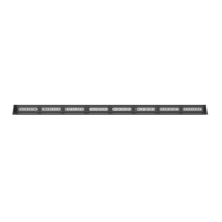
STL Striker®- 8 TIR LED Trac Advisor
Operation Manual and Instructions
Congratulations, you are the owner of a STL Striker®-8 TIR LED Trac Advisor! Your bar is equipped with the latest technology and features at the
best value found industry wide, GUARANTEED. In addition to that, your purchase comes with the STL 5 Year Warranty against any manufacture
defects that may occur with your bar. So please read this document carefully and call Customer Service at 800-757-8581 Monday - Friday 8:30 AM
- 8:30 PM central time if you need assistance. We are available and happy to help!
Warnings and Notices for Users and Installers
This document must be delivered to and read by the end user and installer as it serves to provide you with the required information for proper and
safe use of your STL product. Before operating this or any STL products the user and installer must read this manual all the way through. You will
nd important information in this manual that could prevent property damage and/or serious injury to the user and installer.
STL products are intended to alert pedestrians and other operators of the presence of personnel, the operation of emergency vehicles, an emer-
gency site, and any warning needs. This does not ensure that pedestrians or drivers will react, heed, or observe emergency warning signals. Nor
does the use of emergency signals grant or ensure you the right of way. It is your responsibility to make sure you can proceed safely before driving
against trac, entering an intersection, responding at a high rate of speed, or walking on or around trac lanes.
Your STL emergency vehicle devices should be tested daily to insure the device and all its functions are operating correctly. If you experience a
malfunction contact STL’s Customer Service immediately for troubleshooting options, or a warranty or service claim. You must ensure sure that
the projection of the visual and audible signal is not blocked by vehicle components (i.e.: open trunks, visors, compartment doors), vehicles, other
obstructions, or people.
This is professional grade equipment and is intended for strict use by authorized personnel only. It is the user’s responsibility to understand and
obey all laws regarding emergency warning devices. You must know and be familiar with all applicable city, state, and federal laws and regulations
prior to the use of emergency vehicle warning devices.
SpeedTech Lights, Inc. assumes no liability for any loss resulting from the use of this warning device. Proper installation is vital to the performance
of the warning devices and safe operation of the emergency vehicle. Since the operator is under stressful environments the equipment must be
properly wired and mounted to ensure eectiveness and safety. Therefore controllers must be properly installed and placed within convenient
reach of the operator so eye contact with the roadway is never lost.
The eectiveness of your STL equipment is highly dependent upon correct mounting and wiring. Improper wiring and mounting of the warning
device will reduce the output and performance of the equipment. Emergency warning devices frequently require high electrical voltages and/
or currents. Properly protect and use caution around live electrical connections. Grounding or shorting of electrical connections can cause high
current arcing, which can cause severe personal injury and/or serious vehicle damage, including re.
Electromagnetic interference can be caused by many electronic devices used in emergency vehicles. To ensure that this doesn’t happen to you,
lightbars should be mounted a minimum of 12” - 34” from the radio antenna and do not power your equipment from the same circuit or share the
same grounding circuit with radio communication equipment. After installation, test all the vehicle’s equipment together to ensure everything
operates free of interference.
Driver and/or passenger airbags bags (SRS) will impact the way you mount your equipment. Any equipment installed in the deployment area of
the airbags will damage or dislodge the airbags and sensors. This will also reduce the eectiveness of the airbags to protect the passengers and
therefore these areas must be avoided. Installers must make sure that this equipment along with any parts, hardware, wiring, power supplies, and
switch boxes do not interfere with the airbags, SRS wiring, or sensors.