Specications
9/14
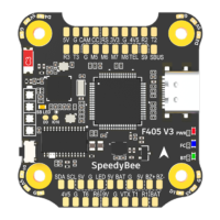
Product Name SpeedyBee F405 V3 30x30 Flight Controller
MCU STM32F405
IMU(Gyro) ICM42688P
USB Port Type Type-C
Barometer Built-in
OSD Chip AT7456E chip
BLE Bluetooth
Wireless FC Firmware Flashing
Wireless Blackbox
Dwonload & Analysis
Supported. Used to connect with the SpeedyBee App for flight controller and ESC parameter
configuration. Please make sure the MSP switch on UART 4 is turned on and set to a baud
rate of 115200, otherwise Bluetooth functionality will not be available.
WIFI Not supported
NOT Supported.
Please connect to the Betaflight configurator on the PC to do FC firmeare update.
NOT Supported.
Please connect to the Betaflight configurator on the PC to do blackbox analysis.
DJI
Air Unit Connection W
ay Direct soldering
DJI Air Unit Compatibility
Compatible with all DJI Air Units: DJI O3/RunCam Link/Caddx Vista/DJI Air Unit V1. Please
use the solder pads <9V, G, T1, R1, G, SUBS(R2)> on the front right corner of the flight
controller to make a pin-to-pin connection with the solder pads on the DJI Air Unit.
UART1(T1, R1) is used for OSD and SUBS(R2) is used for DJI Air Unit’s internal SBUS
receiver signal input.
Blackbox
8MB Onboard Flash
BetaFlight Camera Control Pad
Yes(CC pad on the front side)
Current Sensor Input Supported. For SpeedyBee BLS 35A V2 ESC, please set Scale=250 and Offset=-500.
Power Input
3-6S LiPo. The flight controller is powered through the G, V wires of the 8pin harness
or G, V pads from the bottom side of the flight controller.
5V Output
4 groups of 5V output, three +5V pads and 1 BZ+ pad( used for Buzzer) on front side.
The total current load is 2A.
9V Output
3.3V Output
4.5V Output
ESC Signal
UART
ESC Telemetry
I2C
Traditional Betaflight LED Pad
Buzzer
BOOT Button
RSSI Input
Smart Port / F.Port
Supported Flight Controller Firmware
Firmware Target Name
Mounting
Dimension
Weight
1 group of 9V output, one +9V pad on front side. The total current load is 3A.
Supported. Soldering pad named ‘3V3’ on the front top of the flight controller. Designed
for 3.3V input receivers. Up to 500mA current load.
Supported. Designed for radio receiver and GPS module even when the FC is powered
through the USB port. Up to 1A current load.
M1 - M4 wires or soldering pads on bottom side.
6 sets(UART1, UART2, UART3, UART4(Dedicated for Bluetooth connection)),
UART5(Dedicated for ESC telemetry),UART6
UART R5(UART5)
Supported. DA & CL pads on front side. Used for magnetometer, sonar, etc
Supported. 5V, G and LED pads on bottom of the front side. Used for WS2812 LEDs
controlled by the Betaflight firmware.
BZ+ and BZ- pad used for 5V Buzzer
Supported. Press and hold BOOT button and power the FC on at the same time will force
the FC to enter DFU mode, this is for firmware flashing when the FC gets bricked.
Not Supported
Not Supported
BetaFlight(Default), INAV
SPEEDYBEEF405MINI
30(L) x 32(W) x 7.8(H)mm
9.6g
20 x 20mm 3.5mm hole diameter,Compatible with M2 and M3 screws/Silicone grommets.
 Loading...