EasyManua.ls Logo

SpeedyBee F405 Mini BLS - User Manual

Default Icon
14 pages
Print Icon
To Next Page IconTo Next Page
Loading...
F405
Mini
F405 Mini BLS
35A 20x20 Stack
User Manual V1.0
(Click on any section to jump)
Contents
Pa 1 - OverView
Specs Oveiew
Dimensions
Package
FC & ESC Connection
Pa 2 - SpeedyBee F405 Mini Flight Controller
Layout
FCs Peripheral Connection
App & FC Conguration
FC Firmware Update
Specications
Pa 3 - SpeedyBee BLS 35A Mini V2 4-in-1 ESC
Layout
Connection with Motors & Power Cable
ESC Conguration
ESC Firmware Update
Specications
2
1
1
3
4
5
5
6
7
8
9
10
10
11
12
13
14
F405 Mini BLS
35A 20x20 Stack
F405
Mini
P
a 1
1/14
Oveiew
Specs Oveiew
1/14
Product Name
Flight Controller
ESC
Bluetooth
WiFi
Wireless FC
Firmware Flashing
Wireless Blackbox
Dwonload & Analysis
Power Input
Mounting
Dimension
Weight
SpeedyBee F405 Mini BLS 35A 20x20 Stack
SpeedyBee F405 Mini
SpeedyBee BLS 35A Mini V2 4-in-1 ESC
Suppoed. Used to connect with the SpeedyBee App for
ight controller and ESC parameter conguration. Please
make sure the MSP switch on UART 4 is turned on and
set to a baud rate of 115200, otherwise Bluetooth
functionality will not be available.
NOT Suppoed
NOT Suppoed
NOT Suppoed
3-6S LiPo
20 x 20mm
3.5mm hole size,Compatible with M2 and
M3 screws/Silicone grommets.
32mm(L) x 35mm(W) x 14.2mm(H)
13.5g
Question and Answer IconNeed help?

Do you have a question about the SpeedyBee F405 Mini BLS and is the answer not in the manual?

Summary

Part 1: Overview

Specs Overview

Overview of product specifications including name, controller, ESC, connectivity, and power.

Dimensions

Detailed physical dimensions of the SpeedyBee F405 Mini stack, shown with diagrams.

Package Contents

Lists all included components and accessories for the SpeedyBee F405 Mini stack.

FC & ESC Connection

Instructions for connecting the Flight Controller (FC) and Electronic Speed Controller (ESC) using cables or soldering.

Part 2: SpeedyBee F405 Mini Flight Controller

Layout

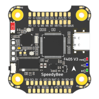
Diagram identifying key components and ports on the SpeedyBee F405 Mini Flight Controller.

LED Indicator Definition

Explanation of the color codes and status indications for the LEDs on the flight controller.

BOOT Button Functionality

Procedure for using the BOOT button to re-flash firmware on a bricked flight controller.

FCs Peripheral Connection

Diagrams showing connections for various peripherals like receivers, GPS, and VTX to the FC.

DJI Air Unit Cable Connection

Specific instructions for connecting DJI Air Unit O3, Caddx Vista, or Air Unit V1.

SBUS Receiver Connection Notice

Important information regarding SBUS receiver connections, especially when using DJI Air Unit.

ELRS Receiver Connection Notice

Important information regarding ELRS receiver connections, especially when using DJI Air Unit.

SpeedyBee App Configuration

Guide to downloading and using the SpeedyBee app for configuring the flight controller.

FC Configuration Steps

Steps to connect and configure the flight controller using the SpeedyBee app, including accelerometer calibration.

FC Firmware Update

Instructions for updating the flight controller firmware using a PC and Betaflight configurator.

Flight Controller Specifications

Detailed technical specifications for the SpeedyBee F405 Mini Flight Controller.

Part 3: SpeedyBee BLS 35 A Mini V2 4-in-1 ESC

ESC Layout

Diagram identifying key components and connection points on the SpeedyBee BLS 35A Mini V2 4-in-1 ESC.

Motor and Power Connection

Instructions for connecting motors and the power cable (XT30) to the ESC, including capacitor placement.

ESC Configuration

Guide to configuring the ESC using the SpeedyBee app or PC-based ESC configurator.

ESC Firmware Update

Instructions for updating the ESC firmware (BLHeliS/Bluejay) using the ESC-configurator website.

ESC Specifications

Detailed technical specifications for the SpeedyBee BLS 35A Mini V2 4-in-1 ESC.

Overview

The SpeedyBee F405 Mini BLS 35A 20x20 Stack is a compact and integrated flight control system designed for FPV drones, combining a flight controller (FC) and a 4-in-1 Electronic Speed Controller (ESC). This stack is built for performance and ease of use, offering a range of features for both beginners and experienced pilots.

Function Description

The SpeedyBee F405 Mini BLS 35A 20x20 Stack serves as the central control unit for a drone. The F405 Mini Flight Controller, based on the STM32F405 MCU and ICM42688P gyro, processes flight commands, stabilizes the drone, and manages various peripherals. It features a built-in barometer for altitude holding, an AT7456E OSD chip for on-screen display of flight data, and a Type-C USB port for configuration. The integrated Bluetooth module allows for wireless configuration via the SpeedyBee App, simplifying field adjustments.

The SpeedyBee BLS 35A Mini V2 4-in-1 ESC is responsible for controlling the speed of the drone's motors. It supports BLHeli_S firmware (J-H-40) and DSHOT300/600 ESC protocols, providing precise and responsive motor control. With a continuous current rating of 35A per motor (4 motors total) and a burst current of 45A for 5 seconds, it can handle demanding flight conditions. The ESC also includes a current sensor, providing real-time current draw data to the flight controller.

The stack is designed for seamless integration, with an 8-pin JST cable connecting the FC and ESC, simplifying wiring and reducing clutter. It supports a wide range of peripherals, including various receiver types (Spektrum, PPM, ELRS, SBUS), LED strips, GPS modules, buzzers, and DJI Air Units (O3, Link, Vista, V1).

Important Technical Specifications

Flight Controller (SpeedyBee F405 Mini):

  • MCU: STM32F405
  • IMU (Gyro): ICM42688P
  • USB Port: Type-C
  • Barometer: Built-in
  • OSD Chip: AT7456E
  • Bluetooth: Supported (for SpeedyBee App configuration, requires MSP switch on UART 4 at 115200 baud rate)
  • Wireless FC Firmware Flashing: Not Supported (requires PC connection)
  • Wireless Blackbox Download & Analysis: Not Supported (requires PC connection)
  • WiFi: Not Supported
  • DJI Air Unit Compatibility: Compatible with DJI O3/RunCam Link/Caddx Vista/DJI Air Unit V1. Utilizes 9V, G, T1, R1, G, SBUS(R2) solder pads for connection. UART1 (T1, R1) for OSD, SBUS(R2) for DJI Air Unit's internal SBUS receiver.
  • Blackbox: 8MB Onboard Flash
  • BetaFlight Camera Control Pad: Yes (CC pad on the front side)
  • Current Sensor Input: Supported (for SpeedyBee BLS 35A V2 ESC, Scale=250, Offset=-500)
  • Power Input: 3-6S LiPo (powered via G, V wires of 8-pin harness or G, V pads from bottom side)
  • 5V Output: 4 groups (three +5V pads, one BZ+ pad for Buzzer), 2A total current load.
  • 9V Output: 1 group (+9V pad), 3A total current load.
  • 3.3V Output: 3V3 pad on front top, 500mA current load (for 3.3V input receivers).
  • 4.5V Output: For radio receiver and GPS module, 1A current load (even when FC is USB powered).
  • ESC Signal: M1-M4 wires or soldering pads on bottom side.
  • UART: 6 sets (UART1, UART2, UART3, UART4 (Dedicated for Bluetooth), UART5 (Dedicated for ESC telemetry), UART6).
  • ESC Telemetry: UART R5 (UART5)
  • I2C: Supported (DA & CL pads for magnetometer, sonar, etc).
  • Traditional Betaflight LED Pad: Supported (5V, G and LED pads on bottom side for WS2812 LEDs).
  • Buzzer: BZ+ and BZ- pad for 5V Buzzer.
  • BOOT Button: Supported (press and hold BOOT button and power FC to enter DFU mode for firmware flashing).
  • RSSI Input: Not Supported
  • Smart Port / F.Port: Not Supported
  • Supported Flight Controller Firmware: BetaFlight (Default), INAV
  • Firmware Target Name: SPEEDYBEEF405MINI
  • Mounting: 20 x 20mm, Φ3.5mm hole size, compatible with M2 and M3 screws/Silicone grommets.
  • Dimension: 30mm(L) x 32mm(W) x 7.8mm(H)
  • Weight: 9.6g

ESC (SpeedyBee BLS 35A Mini V2 4-in-1 ESC):

  • Firmware: BLHeli_S J-H-40
  • Continuous Current: 35A * 4
  • Burst Current: 45A (5 seconds)
  • ESC Protocol: DSHOT300/600
  • Power Input: 3-6S LiPo
  • Power Output: VBAT (Battery voltage, used to power the flight controller)
  • Current Sensor: Support (Scale=250, Offset=-500)
  • Mounting: 20 x 20mm, Φ3.5mm hole size, compatible with M2 and M3 screws/Silicone grommets.
  • Dimension: 35mm * 35mm * 5.5mm
  • Weight: 7.2g

Overall Stack:

  • Mounting: 20 x 20mm, Φ3.5mm hole size, compatible with M2 and M3 screws/Silicone grommets.
  • Dimension: 32mm(L) x 35mm(W) x 14.2mm(H)
  • Weight: 13.5g

Usage Features

  • Easy Connection: The FC and ESC connect directly via an 8-pin JST cable, simplifying the build process. Direct soldering is also an option for custom setups.
  • Wireless Configuration: The built-in Bluetooth module allows for convenient wireless configuration of both the FC and ESC parameters using the SpeedyBee App on a smartphone. This eliminates the need for a PC in the field for minor adjustments.
  • Comprehensive App Support: The SpeedyBee App provides a user-friendly interface for configuring flight controller settings (PIDs, rates, modes), updating ESC firmware (for BLHeli_S or Bluejay), and monitoring flight data.
  • DJI Air Unit Compatibility: Dedicated solder pads and wiring instructions are provided for seamless integration with various DJI Air Units, ensuring compatibility with popular digital FPV systems.
  • Receiver Flexibility: Supports a wide range of receiver types, including Spektrum, PPM, ELRS, and SBUS, catering to different radio systems. Specific instructions are provided for SBUS and ELRS receivers, including important notes on disconnecting conflicting wires when using DJI Air Units simultaneously.
  • LED Indicators: Features Red (Power), Green (Bluetooth status), and Blue (FC status) LEDs for quick visual feedback on the stack's operational status.
  • Low ESR Capacitor Recommendation: It is strongly recommended to use the included Low ESR capacitor with the ESC to prevent voltage spikes during power-up, which can protect the stack from damage.
  • Multiple Power Outputs: Provides various regulated power outputs (5V, 9V, 3.3V, 4.5V) for powering peripherals like cameras, VTXs, GPS modules, and receivers, reducing the need for external BECs.

Maintenance Features

  • Firmware Flashing:
    • FC Firmware: While wireless FC firmware flashing is not supported, the FC can be updated via a PC using Betaflight/INAV configurator. A BOOT button is provided for entering DFU mode in case the FC gets bricked, allowing for re-flashing.
    • ESC Firmware: The ESC firmware (BLHeli_S or Bluejay) can be updated wirelessly through the SpeedyBee App or via a PC using the ESC Configurator (accessible through a Google Chrome browser).
  • Troubleshooting: The BOOT button on the FC is a critical tool for recovery in case of firmware issues, allowing users to force the FC into DFU mode for re-flashing.
  • Clear Wiring Diagrams: The manual provides detailed wiring diagrams for connecting various peripherals, simplifying installation and troubleshooting.
  • Community Support: The SpeedyBee ecosystem often benefits from active community support and regular firmware updates, ensuring ongoing improvements and bug fixes.
  • Component Protection: The inclusion of a TVS Diode on both the FC and ESC helps protect against voltage spikes, enhancing the durability and longevity of the stack.

SpeedyBee F405 Mini BLS Specifications

General IconGeneral
BrandSpeedyBee
ModelF405 Mini BLS
CategoryDrone & Quadcopter Accessories
LanguageEnglish

Related product manuals