9/14
Specications
Product Name
MCU
IMU(Gyro)
USB Po Type
Barometer
OSD Chip
BLE Bluetooth
WIFI
DJI Air Unit Connection Way
6-pin DJI Air Unit Plug
Blackbox MicroSD Card Slot
Current Sensor Input
Power Input
5V Output
9V Output
3.3V Output
4.5V Output
ESC Signal
UART
ESC Telemet
I2C
Traditional Betaight LED Pad
Buzzer
BOOT Button
RSSI Input
Sma Po / F.Po
Suppoed Flight Controller
Firmware
Firmware Target Name
Mounting
Dimension
Weight
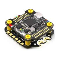
SpeedyBee F405 V4 30x30 Flight Controller
STM32F405
ICM42688P
Type-C
Built-in
AT7456Echip
Suppoed. Used for Flight Controller conguration
(MSP should be enabled with Baud
rate 115200 on UART4)
Not suppoed
Two ways suppoed: 6-pin connector or direct soldering.
Suppoed. Completely compatible with DJI O3/RunCam Link/Caddx Vista/DJI Air Unit V1,
no wire is needed to be changed.
*Betaight rmware requires the type of the microSD card to be either Standard (SDSC) or
High capacity (SDHC) under 32GB, so extended capacity cards (SDXC) are not suppoed
(Many high-speed U3 cards are SDXC). Also the microSD card MUST be formatted with the
FAT16 or FAT32 (recommended) format. So, you could use any SD card less than 32GB, but the
Betaight can only recognize 4GB maximum. We suggest you use this
3rd pay formatting
tooland choose 'Overwrite format' then format your card. Also check outherefor the
recommended SD cards or buy thetested cardsfrom our store.
Suppoed. For SpeedyBee BLS 55A ESC, please set scale = 400 and Oset = 0.
3S - 6S Lipo(Through G, BAT pins/pads from the 8-pin connector or 8-pads on the bottom side)
9 groups of 5V output, four +5V pads and 1 BZ+ pad( used for Buzzer) on front side, and
4x LED 5V pads. The total current load is 3A.
2 groups of 9V output, one +9V pad on front side and other included in a connector on
bottom side. The total current load is 3A.
Suppoed. Designed for 3.3V-input receivers. Up to 500mA current load.
Suppoed. Designed for receiver and GPS module even when the FC is powered through the
USB po. Up to 1A current load.
M1 - M4 on bottom side and M5-M8 on front side.
6 sets(UART1, UART2, UART3, UART4(Dedicated for Bluetooth connection)), UART5
(Dedicated for ESC telemet),UART6
UART R5(UART5)
Suppoed. SDA & SCL pads on front side. Used for magnetometer, sonar, etc.
Suppoed. 5V, G and LED pads on bottom of the front side. Used for WS2812 LED
controlled by Betaight rmware.
BZ+ and BZ- pad used for 5V Buzzer
Suppoed.
[A]. Press and hold BOOT button and power the FC on at the same time will force the
FC to enter DFU mode, this is for rmware ashing when the FC gets bricked.
[B]. When the FC is powered on and in standby mode, the BOOT button can be used to
controller the LED strips connected to LED1-LED4 connectors on the bottom side.
By default, sho-press the BOOT button to cycle the LED displaying mode. Long-press
the BOOT button to switch between SpeedyBee-LED mode and BF-LED mode. Under
BF-LED mode, all the LED1-LED4 strips will be controlled by Betaight rmware.
Suppoed. Named as RS on the front side.
Not suppoed
BetaFlight(Default), INAV
SPEEDYBEEF405V4
30.5 x 30.5mm( 4mm hole diameter)
41.6(L) x 39.4(W) x 7.8(H)mm
10.5g