Do you have a question about the Spellman XRV160*1800 and is the answer not in the manual?
Classifies the XRV SERIES as a Class I device based on safety requirements for electrical equipment.
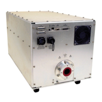
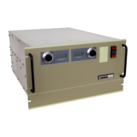
Describes the XRV SERIES as a high voltage switching power supply for X-ray tubes and other loads.
Discusses the device's design to minimize electromagnetic interferences and test results.
Details the unit's high voltage potential output for X-ray tubes and dual DC filament supplies.
Displays safety-related symbols used on the unit: Caution, High-voltage connection, and Ground connection.
Details the connector layout and identification for the XRV 160kV Cathode model's rear panel.
Details the connector layout and identification for the XRV 160kV Anode model's rear panel.
Details the connector layout and identification for the XRV 225kV Cathode model's rear panel.
Details the connector layout and identification for the XRV 225kV Anode model's rear panel.
Specifies the input voltage requirements for the XRV Power Supply, noting it is not field selectable.
Details the pin configuration and voltage for the main and auxiliary AC input power connector.
Instructions for connecting the system ground wire to the power supply.
Explains how to connect interlocks, pre-warning, and X-RAY ON indicator to the J2 connector.
Provides a system interconnection and setup diagram for single-ended configurations.
Provides a system interconnection and setup diagram for bi-polar configurations.
Details the pin assignments (HV Output, Small Filament, Large Filament) for the HV connector J1.
Provides step-by-step instructions for installing the HV cable, including safety precautions.
Describes control via RS232, Ethernet, and USB interfaces, including connection details.
Details the analog interface connector J2 for manual control and logic signals.
Overview of the XRV SERIES as a high voltage switching power supply for X-ray tubes.
Describes the control board functions, including digital circuitry, ADCs, DACs, and DSP.
Explains the function and operation of the kV regulator circuit, including feedback and ramp-up.
Details the mA regulator's function, similar to kV regulator, controlling the filament inverter.
Details how faults are detected, latched by the DSP, and indicated via front panel LEDs and GUI.
Explains the arc detection mechanism, quenching, and counter functionality.
Describes the components of the inverter module assembly, including EMI filter and power inverter board.
Details the filament inverter operation and the kV/mA feedback calibration circuitry.
Describes the HV Transformer assembly and its role in stepping up the voltage for the HV multiplier.
Details the HV section, including HV multiplier, current limiting, and HV divider components.
Guides on changing user settings, operating limits, and filament parameters via GUI or analog control.
Provides system requirements and instructions for installing the XRV GUI software from CD or FTP.
Outlines minimal maintenance requirements, focusing on fan filter cleaning and HV plug connections.
Information on how to identify and diagnose faults using front panel LEDs or GUI control.
Procedure for calibrating filament current for both large and small filaments using test equipment.
| Brand | Spellman |
|---|---|
| Model | XRV160*1800 |
| Category | Power Supply |
| Language | English |