Do you have a question about the Spellman SL Series and is the answer not in the manual?
General safety guidelines for operating the high voltage power supply.
Safety precautions specifically for servicing the high voltage equipment.
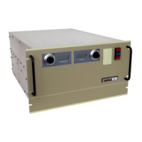
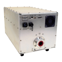
Overview of the SL Series high voltage power supplies, highlighting features and design.
Details on standard features designed to optimize user satisfaction and safety.
Explanation of features for remote control and monitoring of the power supply.
Description of indicators providing system operation and fault condition information.
List and brief description of available optional features for the SL Series.
Guide to understanding the model number nomenclature for SL Series power supplies.
Procedures for inspecting the unit and its packaging upon receipt.
Guidelines for mounting and installing the SL Series power supply unit.
Step-by-step instructions for the safe and proper operation of the power supply.
Details on standard features related to remote interface and signal grounding.
Description of the physical construction and capabilities of the SL Series chassis.
Explanation of the AC to DC conversion and filtering process for the power supply.
Details on the high frequency inverter topology and control scheme.
Description of the high voltage transformer's role and typical specifications.
Explanation of the high voltage assembly, including its variations and filtering.
Overview of the control and power printed wiring board functions and circuitry.
Description of the front panel components, meters, and interface connections.
Discussion of how variations in models and options affect circuit descriptions.
Details on the overload trip protection feature that shuts down output on overcurrent.
Information on SL Series power supplies operating from a 220Vac input.
Description of the option that causes output voltage to rise rapidly on power on.
Option to set a custom rise time for the output voltage.
Specification for ordering output cables longer than the standard 10 feet.
Option providing isolation of the power supply common from chassis ground.
Low leakage floating ground option with reduced current leakage specification.
Options for monitoring and controlling power supply output power.
Option to trip the unit to Standby after sensing a single arc.
Details on the option to reverse the polarity of the output voltage.
Option enabling high voltage as soon as line voltage is applied.
Option for two supplies of opposite polarity to function as a tracking bipolar supply.
Provides customer accessible relay contacts controlled by fault status circuitry.
Information on units built to customer specifications with an assigned X number.
Recommended procedures for periodic servicing, including cleaning and inspection.
Details on performance testing procedures and required test equipment.
Description of high voltage dividers available for precise voltage measurements.
Information on obtaining parts lists and ordering replacement parts for specific models.
Guidelines for correspondence and ordering spare parts, including necessary information.
Details on warranty repair services provided by Spellman.
Procedures for returning units for calibration or repair at the factory.
Information on retrofitting options and modifications by the factory.
Guidelines for securely packing and shipping units for factory service.
Description of how to operate the eSL unit using the local front panel controls.
Details on the Ethernet communications protocol used by the eSL unit.
Configuration of network settings for the eSL unit, including IP address and port.
Procedure to reset the Ethernet port settings to their default factory configuration.
Description of message format when transmitting data from the host to the eSL unit.
Description of messages sent from the eSL unit to the host, including acknowledgments and errors.
Reference for commands used to control the eSL unit, including Set KV, Get mA, etc.
Step-by-step guide for downloading and installing the eSL GUI software.
Instructions for setting up communication between the eSL GUI and the unit.
Overview of the main menu in the eSL GUI for controlling and monitoring the unit.
Display of monitored HV power, system voltages, and units in Watts.
Interface for user configuration of settings like Slow Start, Arc Control, and AOL.
Information about the eSL GUI, including part numbers and revision status for troubleshooting.
| Input Voltage | 100-240VAC, 50/60Hz |
|---|---|
| Polarity | Positive, Negative |
| Ripple | <0.1% |
| Operating Temperature | 0°C to 40°C |
| Storage Temperature | -20°C to 70°C |
| EMC Standards | EN 61326-1 |
| Dimensions | Varies by model |
| Weight | Varies by model |