SL SERIES MANUAL 13 118006-001 REV Y
+
Remote
1
2
3
4
5
6
7
8
9
10
11
Current
Program
V
V
Remote
Voltage
Program
+
Remove jumpers for
remote programing
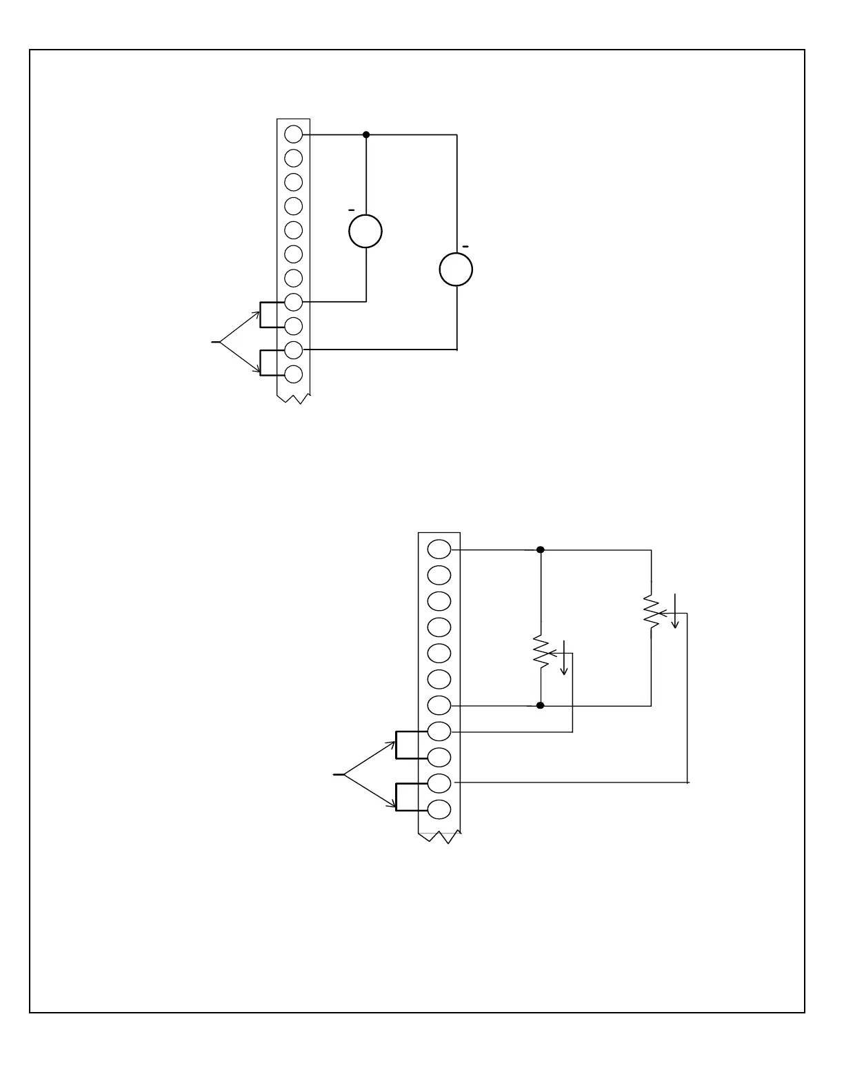
Voltage Source 0-10V = 0-100% of Rated Output
It is recommended that analog signals be isolated
via isolation amplifiers.
All cables should be shielded w ith the shields
being returned to the chassis ground of the
High Voltage Power Supply.
TB1/J5
PS Common
Z in = 10M
Z in = 10M
1
2
3
4
5
6
7
8
9
10
11
Remote
Current
Control
Remote
Voltage
Control
Z in = 10M
Z in = 10M
Remove jumpers for
remote programing
All cables should be shielded with the shields
being returned to the chassis ground of the
High Voltage Pow er Supply.
TB1/J5
20k
20k
CW
CW
+10.32V
1mA max.
PS Common
Fully Counterclockw ise = Zero Output
Fully Clockw ise = 100% of Rated Output
If connections to external potentiometers are
excessively long (>10ft), motorized
potentiometers are recommended.
Figure 3.2B -- Wiring Diagram for Remote Programming Via External
Figure 3.2A -- Wiring Diagram for Remote Programming Via Voltage



 To Next Page