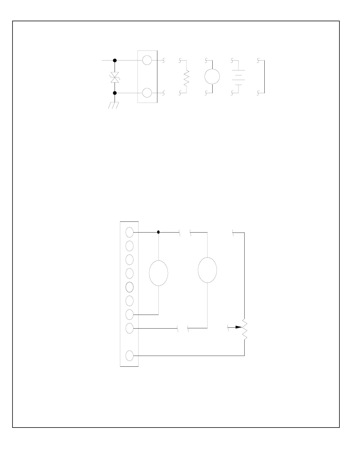
EasyManua.ls Logo

Spellman SL Series - Figure 5.1 Floating Ground Interface Circuit; Figure 5.2 Adjustable Power Remote Interface TB1 Only

Default Icon
68 pages
Print Icon
To Next Page IconTo Next Page
To Previous Page IconTo Previous Page
Loading...
SL SERIES MANUAL 24 118006-001 REV Y
Remote
Power
Program
3
4
2
-
M
1
V
-
TB1
Remove internal
jumper, JP1 ON
Control/Pwr PWB
for remote
Programing. (Jumper
connects internal,
pot, factory set at
103% of max power).
Remote
Power
Monitor
0-10V
=0-100%
power
output
Zout=
4.99k ohm 0.1%
20K ohm
min.
Z in = 10M ohm
7
13
6
12
5
+
+
Remote Power
Programming
potentiometer
M
1
2
high voltage
return circuits.
Pin 2 internally
connected to
pow er supply
chassis.
* IMPORTANT: Pow er dissipation
in CR1 should not exceed 1/2W.
This can be accomplished by
keeping TB3-1 and TB3-2
voltage below Zener voltage.
CR1 is for safety and transient
protection only, and is not
designed for continuous clamping.
Possible FG termination circuits
TB2
CR1
units are
shipped w ith
external
Up to 50V is available.
Consult factory.
To internal
FG option
jumper.
Zener voltage is 18V standard.
Figure 5.1 -- Floating Ground Interface Circuit
Figure 5.2 -- Adjustable Power Remote Interface TB1 Only

Table of Contents

Related product manuals