EasyManua.ls Logo

Spellman SL Series - Table 3.2 Rear Panel Interface 25 Pin Mini D

Default Icon
68 pages
Print Icon
To Next Page IconTo Next Page
To Previous Page IconTo Previous Page
Loading...
SL SERIES MANUAL 12 118006-001 REV Y
J5
SIGNAL
SIGNAL PARAMETERS
1
Power Supply Common
Signal Ground
2
External Inhibit
Ground = Inhibit, Open = HV ON
3
External Interlock
+15V at Open, <15mA at Closed
4
External Interlock Return
Return For Interlock
5
Current Monitor
0 to 10V = 0 to 100% Rated Output
6
kV Test Point
0 to 10V = 0 to 100% Rated Output
7
+10V Reference
+10.24V, 1mA Max
8
Remote Current Program In
0 to 10V = 0 to 100% Rated Output
9
Local Current Program Out
Front Panel Program Voltage
10
Remote Voltage Program In
0 to 10V = 0 to 100% Rated Output
11
Local Voltage Program Out
Front Panel Program Voltage
12
EFR (Common)
Optional External Fault Relay
13
EFR (Normally Open)
14
Local HV Off Out
+15V at Open, < 25mA at Closed.
Connect to HV OFF For FP Operation
15
HV OFF
16
Remote HV ON
+15V, 10mA Max = HV ON
17
Remote HV OFF Indicator
0 = HV ON, +15V, 10mA Max = HV OFF
18
Remote HV ON Indicator
0 = HV OFF, +15V, 10mA Max = HV ON
19
Remote Voltage Mode
20
Remote Current Mode
Open Collector 50V Max, 10mA Max On = Active
21
Remote Power Mode
22
Remote PS Fault
0 = Fault, +15V, 0.1 Ma Max = No Fault
23
+15V Output
+15V, 100mA Max
24
Power Supply Common
Signal Ground
25
Shield Return
Chassis Ground
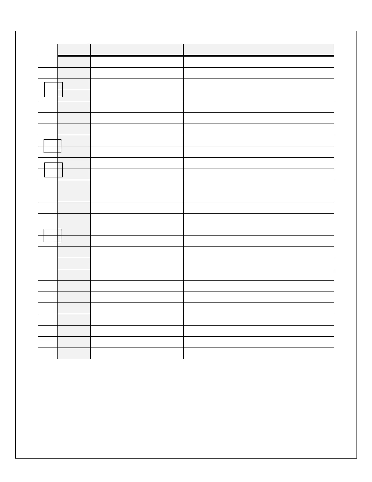
Table 3.2 - Rear Panel Interface 25 pin Mini D

Table of Contents

Related product manuals