10
8. Installation
Please read carefully the following instructions and follow them in the order described
below. The effect of the guarantee cannot be assured if the instructions of this manual
are not followed.
NOTE: None of the 8 wired of the device must be electrically connected. And in case you
do not use the output of any of the solenoids (red and black wire) or any of the inputs
of the counters (white and blue), each of them must be electrically insulated.
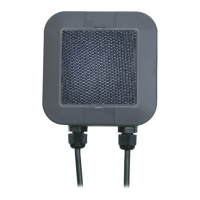
• STEP 1. Connect the device output wires (red and black) to the red and black
wires of the LATCH 12V solenoid type (see Figure 6). In case the solenoid does
not have these colors, the red wire of the ATLAS matches the positive polarity.
Note: the use of sealed connectors is recommended, see Figure 7. (these are purchased
separately).
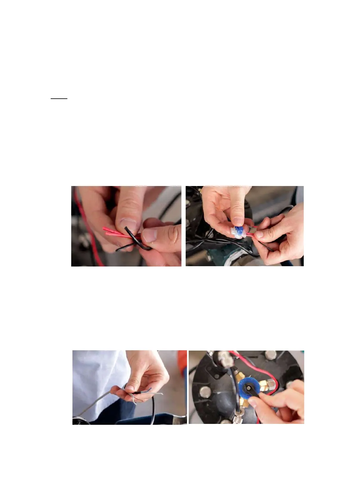
• STEP 2. Connect the device output wires (blue and white) to the wires of the
pulse counter of our installation (brown and white), see Figure 8.
• STEP 3 (Optional). In case of having a three way valve connected to the valve of
the installation, it must be set in the “AUTO” position (see Figure 9).
 Loading...