Do you have a question about the SPHINX Project10 and is the answer not in the manual?
Highlights the high-quality audio design and tradition of the Sphinx name.
Guidance on unpacking the unit and verifying for any shipping damage.
Details on warranty registration and how to contact the manufacturer for support.
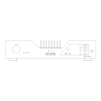
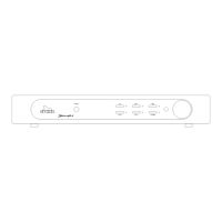
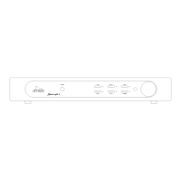
Identifies and describes the function of each control and indicator on the front panel.
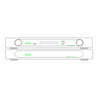
Details all input, output, power, and control connectors on the rear panel.
Explains the function of each button and its corresponding LED on the remote control.
Provides guidance on using the remote for functions like volume and input selection.
Addresses common issues preventing the remote control from working correctly and their solutions.
Describes protection modes, standby operation, and essential checks before servicing.
Lists the necessary measurement equipment and setup for proper amplifier servicing.
Step-by-step guide to adjust the bias current for power transistors.
Procedure to minimize DC offset voltage at the amplifier output.
Addresses the issue of the amplifier not working, primarily due to blown fuses.
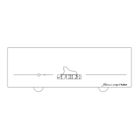
Schematic illustrating the connection setup required for bias adjustment.
Schematic illustrating the connection setup required for offset adjustment.
Diagrams showing connections between main, control, and volume boards.
Overview diagrams of left/right channels, power supply, and input/output boards.
Detailed circuit diagram for the power supply and input selection stages.
Circuit diagram illustrating the volume control board's functionality.
Detailed schematics of the amplifier's left and right channel circuitry.
Circuit diagram for the amplifier's control and processing board.
Information on accessing separate PDF files containing PCB layout drawings.
An extensive list detailing all components used in the Project Ten amplifier.