SPHINX Project Ten Service Manual
2
1. UNPACKING.......................................................................................................................................3
2. SPHINX WARRANTY CARD..............................................................................................................3
3. CONTACTING THE MANUFACTURER.............................................................................................3
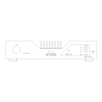
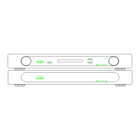
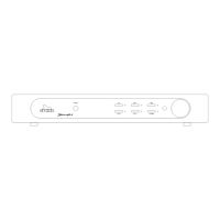
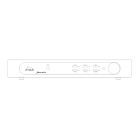
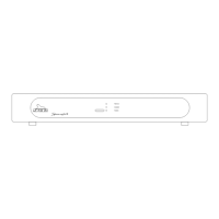
4. THE AMP AT A GLANCE...................................................................................................................4
Front panel................................................................................................................................................... 4
Rear panel ...................................................................................................................................................5
5. SPHINX REMOTE CONTROL............................................................................................................6
Buttons and LED indication..........................................................................................................................6
Operation ..................................................................................................................................................... 7
Selecting without switching .......................................................................................................................... 7
Batteries.......................................................................................................................................................7
Encountering problems................................................................................................................................7
6. TECHNICAL SPECIFICATIONS.........................................................................................................8
7. GENERAL CHECKLIST .....................................................................................................................9
Protection modes......................................................................................................................................... 9
Short Circuit.............................................................................................................................................9
Standby mode.............................................................................................................................................. 9
Necessary Equipment..................................................................................................................................9
8. ADJUSTMENT PROCEDURES........................................................................................................10
Bias............................................................................................................................................................10
Offset .........................................................................................................................................................11
9. PROBLEMS AND SOLUTIONS .......................................................................................................12
10. DIAGRAMS AND PARTS LISTS....................................................................................................13
Connection diagram bias adjustment.........................................................................................................14
Connection diagram offset adjustment.......................................................................................................15
Connections main board and display board of Project 10..........................................................................16
General overview Project 10......................................................................................................................17
Project 10 power supply and input selection..............................................................................................18
Project 10 volume board............................................................................................................................19
Project 10 amplifier left ..............................................................................................................................20
Project 10 amplifier right ............................................................................................................................21
Project 10 control....................................................................................................................................... 22
PCB drawings of Project 10 ....................................................................................................................... 23
Parts list.....................................................................................................................................................24