SPHINX Project Ten Service Manual
5
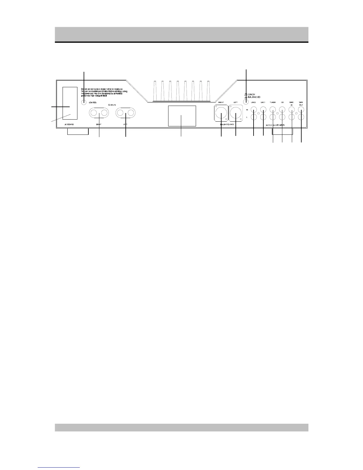
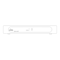
Rear panel
11. ON/OFF: This is the mains power switch.
12. Fuse holder: Contains a fuse (3.15 A slow).
13. AC Power: Connect the mains cable to a mains
power outlet (230 - 240 VAC).
14. CONTROL OUT: To connect the optical cable
going to another Sphinx component.
15. RIGHT OUTPUT: To connect the cable from the
right loudspeaker:
red +
white -
16. LEFT OUTPUT: To connect the cable from the
left loudspeaker:
red +
white -
17. Manufacturer's label: This shows important
data for the component, such as serial number
and mains power voltage.
18. BALANCED LINE 2 RIGHT: To connect the
XLR signal cable (balanced cable) from the right
output of the signal source for Input 2.
19. BALANCED LINE 2 LEFT: To connect the XLR
signal cable (balanced cable) from the left
output of the signal source for Input 2.
20. CINCH/BALANCED: This switch is to select the
input connector for LINE 2:
out LINE 2 (cinch)
in BALANCED LINE 2
21. LINE 2: To connect the cinch signal cable from
the signal source for LINE 2.
22. LINE 1: To connect the cinch signal cable from
the signal source for LINE 1.
23. TUNER: To connect the cinch signal cable from
the tuner.
24. CD: To connect the cinch signal cable from the
CD player.
25. TAPE IN: Connect this input to the output of the
recorder.
26. TAPE OUT: Connect this output to the Input of
the recorder..