3.820.5275.910
6
umidità, temperature dell’ambiente inferiori o supe-
riori ai limiti consentiti (—15°C e +65°C).
B - ATTACCHI E CONNESSIONI
Le connessioni pneumatiche si trovano sul retro del-
la cassetta e sono identificate da apposite lettere.
E - Aria entrata (alimentazione a 20 psi - 1,4 bar)
U - Aria uscita (segnale regolante)
I - Aria integrale (connessione con il dispositivo
integrale di riassetto)
M
1
- Entrata trasm. (collegamento con eventuale
trasmettitore pneumatico)
M
2
- Set point (eventuale collegamento per set
point pneumatico).
Gli attacchi dei collegamenti pneumatici sono da 1/4"
NPT femmina ad esclusione della connessione per
l’aria integrale (I) che è da 1/8" NPT femmina.
La connessione al processo è da 1/4" NPT femmina
per la pressione mentre per i bulbi sensibili alla tem-
peratura si veda la specifica 7B.390.
I regolatori di pressione possono essere equipag-
giati di separatori con attacchi flangiati speciali.
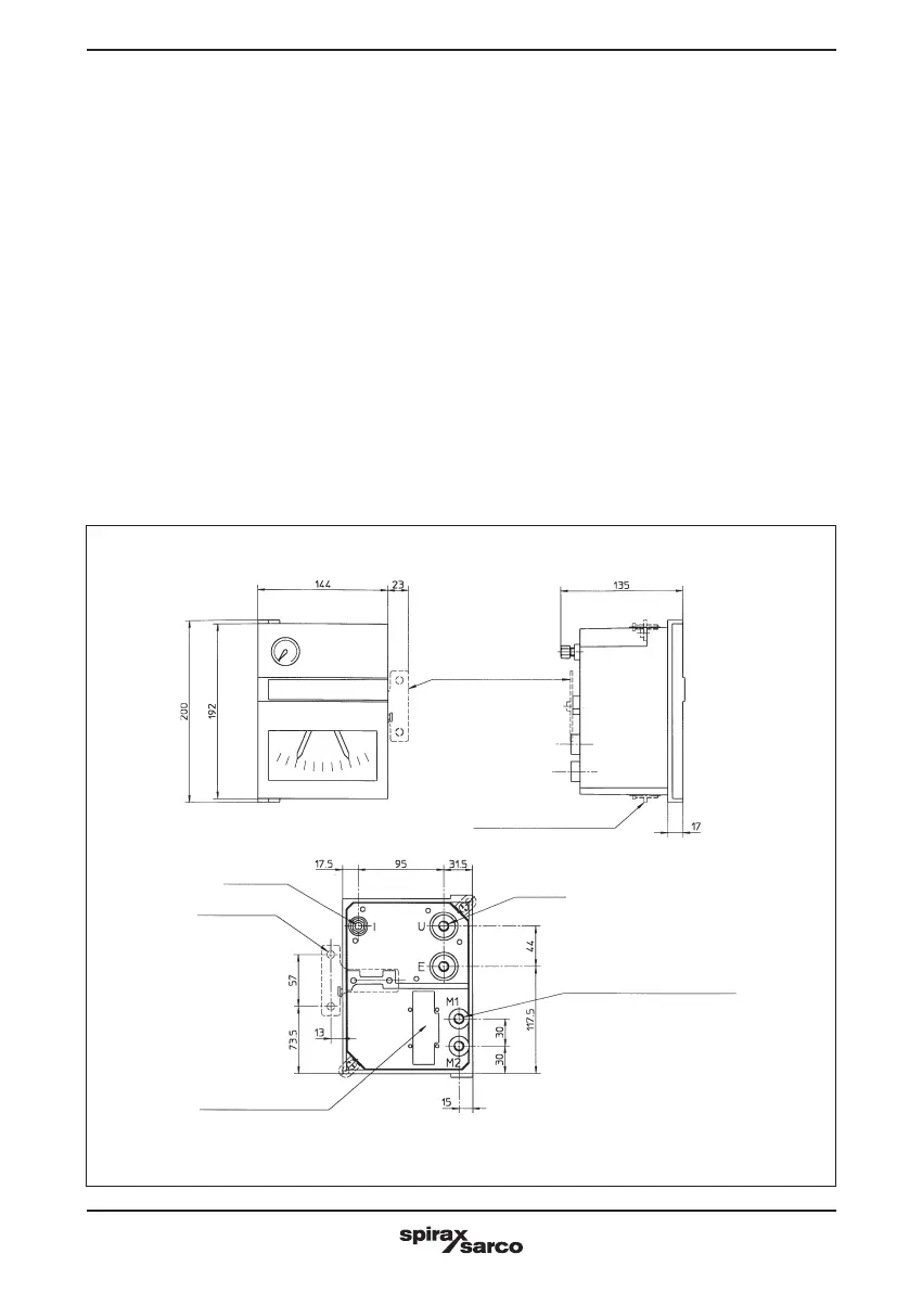
DIMENSIONI DI INGOMBRO E ATTACCHI
minimum and maximum permitted limits.
(—15°C and + 65°C).
B - CONNECTIONS
Pneumatic connections of controllers are fitted on
back of the instrument case and are idendfied by
reference letters.
E - Air inlet (air supply at 20 psi-1.4 bar)
U - Air outlet (output controf signal)
I - Air integral (pneumatic connection to integral
action bellows)
M
1
- Inlet transmitter (pneumatic connection to
transmitter if any).
M
2
- Set point (optional connection for pneumatic
set point).
Standard pneumatic connections are 1/4” size NPT
female with the exception of the air integral connec-
tion (I) that is 1/8” NPT female.
The process connection is 1/4” NPT female for pres-
sure while for the temperature sensing bulb see bulle-
tin 7B.390-E.
Pressure transmitters can be fitted with separators
and flanged connections.
DIMENSIONS AND CONNECTIONS
Fig. 3
Piastra per
montaggio a parete
Wall mounting
support
Piastrine per
montaggio su quadro
Panel
fixing plates
2 fori da 8,3
2 holes
8.3 mm dia.
Presa
manometrica
o termostatica
Pressure
connection
or capillary
inlet
1/8” NPT
1/4” NPT
1/4” NPT Entrata trasmettitore
1/4” NPT Inlet transmitter
 Loading...