3.820.5275.910 9
D - COLLEGAMENTO ALLA VALVOLA PNEUMA-
TICA DI CONTROLLO
Il segnale regolante in uscita dai regolatori ha un va-
lore standard di 3÷15 psi (oppure 0,2÷1 bar). Il se-
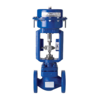
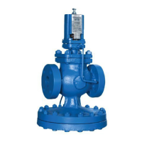
gnale deve essere convogliato alla valvola a dia-
framma (3) con tubo di rame o nylon come in fig. 4.
E’ indispensabile che la linea di collegamento sia
perfettamente stagna, in quanto perdite anche mi-
nime di aria comprometterebbero la trasmissione
dell’azione regolante.
Viene raccomandato un controllo della tenuta del-
la linea cospargendo giunti e raccordi con acqua
saponata od utilizzando appositi spray.
D - PNEUMATIC PIPING TO CONTROL VALVE
The pneumatic control output from the controllers
is a standard 3 to 15 psi (or 0.2 to 1 bar) signal.
Signal must be conveyed to the pneumatic control
valve (3) by means of a copper or nylon tubing as
shown in fig. 4.
lt is essential that this signal line is perfectly airtight,
because even the slightest leakage of air could
modify the characteristics of the control action.
It is therefore recommened that tightness of
fittings and connections of the line are carefully
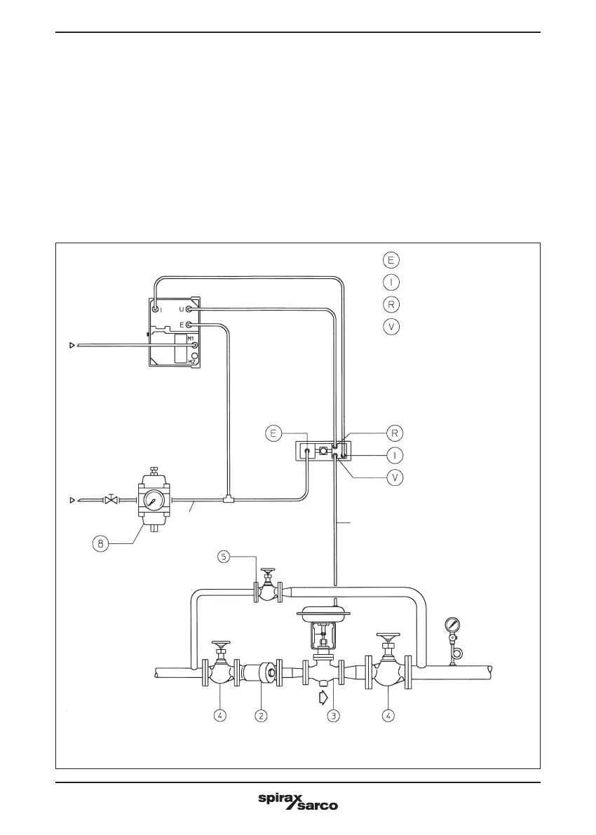
Fig. 6 - Schema tipico di installazione dei regolatori ad azione PI con pannello di commutazione auto-manuale.
Fig. 6 - Typical installation of PI action pneumatic controllers fitted with auto-manual station.
∅ 6x4
Strurnento serie 600
Series 600 instrument
Aria
compressa
Compressed air
20 psi / 1,4 bar
Vista posteriore
pannello
auto manuale
Back view
of auto-manual
station
Aria di alimentazione
Air supply
Collegamento aria integrale
Air integral connection
Segnale regolante dallo strumento
Control output signal from instrument
Alla valvola pneumatica
To pneumatic valve
Dal trasmettitore
Inlet transmitter
(3-15 p.s.i.)
 Loading...